
Abstract
In this paper, a color image encryption method based on finger vein key and off-axis digital holography with phase-modulated reference light is proposed. In the encryption process, firstly the channel separation operation is performed on the color plaintext image, and the “red”, “green” and “blue” channels grayscale data of the color plaintext image are obtained respectively. Subsequently, the finger vein quantum matrix of the encryption user is generated through the quantum matrix generation program and used as the scrambling index key, mask key, and phase mask keys in the next encryption steps. The grayscale data of each channel of the original color plaintext image is then encrypted using the DNA coding encryption operation, and these encrypted results are embedded into the carrier image, thus the encryption watermark image is obtained. After, the encryption watermark image is executed image encryption operation based on double random phase coding (DRPE) in the Fresnel transform ___domain, so that the encryption object light is obtained. Finally, the off-axis digital holography encoding technology (ODHE) with phase-modulated reference light is performed on encryption object light, so that the finally holographic ciphertext is generated. In the decryption process, the decryption user’s finger vein must first be authenticated. If the authentication is successful, the system proceeds with the subsequent decryption steps, so that the correct decrypted color image can be obtained; otherwise, the decryption process is terminated. In order to demonstrate the feasibility of the proposed color image encryption method, a series of numerical simulations are performed, and the simulation results show that the proposed method exhibits high feasibility as well as high security level, large key space, contactless authentication, strong portability of ciphertext, strong robustness and security of finger vein key.
Introduction
Optical color image encryption method has gradually attracted attention from various research groups in recent years because of its fast encryption speed, high security, high parallelism, rich types of keys, and the ability to process large capacity image1,2,3,4. Since the image encryption method based on double random phase coding (DRPE) was proposed by Refregier and Javidi5, optical color image encryption methods have been extensively studied by various research groups and scholars. These methods can mainly be divided into the following six categories based on their underlying optical principles: (1) DRPE-based methods6,7; (2) phase retrieve- based methods8,9,10; (3) equal modulus decomposition-based methods11,12,13; (4) diffractive-imaging-based methods14,15,16; (5) single-pixel-based methods17,18,19; (6) other optical principles-based methods20,21,22,23. However, existing optical color image encryption methods often face the issue of overly complex keys, especially random mask keys are difficult for users to be remembered or carried. Besides, most of optical color image encryption methods also suffer from a critical problem about the lack of connection between user and key, so once the key is lost or stolen, the security information in the system can be obtained by unauthorized attackers through illegal ways.
Biometric keys have been recognized as an effective solution to the aforementioned problems because of their convenience, uniqueness, and resistance to being lost, forgotten, or stolen. In recent years, significant studies on optical color image encryption methods using biometric keys have been conducted by many research groups. For example, Su et al.24 proposed a color image encryption method in multiple transform domains based on fingerprint key and chaotic system. Later, Su et al.25 also proposed a color image encryption method based on fingerprint key and phase-shifted digital holography. Wang et al. proposed an optical single-channel color image encryption method based on chaotic fingerprint phase mask and diffractive imaging26. In addition, the optical image encryption methods based on palmprint27,28 and iris29 has been gradually proposed by Abuturab et al. thus the practicability of optical color image encryption method is gradually expanded.
However, the fingerprint and palmprint keys used in the aforementioned encryption method are traditional biometric keys that require contact-based sensors for authentication, presenting disadvantages such as sensor wear and potential cross-contamination among users. Additionally, because iris data acquisition is highly sensitive to ambient light, it is difficult for the authentication system to accurately capture legitimate users’ iris information under complex lighting conditions, which may lead to decryption failure. Compared to fingerprint, palmprint, and iris keys, the finger vein keys offer natural advantages such as contactless acquisition, easy access, and strong anti-interference capability, making them an effective solution to the aforementioned issues. But, to the best of our knowledge, there is no published paper applying finger vein key to implement optical image encryption method. Additionally, there is also no report on the utilization of off-axis digital holographic coding technique (ODHE) with phase-modulated reference light for the color image encryption method, thus in this paper, a color image encryption method based on finger vein keys and off-axis digital holography with phase-modulated reference light is proposed. In the encryption process, firstly the finger vein image of encryption user is input into the Swi-Transformer network (Swin-TN) for global vein feature extraction so that the finger vein features model is obtained. Subsequently, the finger vein quantum DNA encryption mask (\({\text{VQEM}}\)), finger vein quantum DNA encryption index(\({\text{VQEI}}\)), the first finger vein quantum phase mask (\({\text{VQPM}}_{1}\)), and the second finger vein quantum phase mask (\({\text{VQPM}}_{2}\))are respectively generated by the quantum initial value mapping and the quantum matrix generation program based on quantum walk. Next, the channel separation operation is performed on the color plaintext image, and the “red”, “green” and “blue” channels grayscale data of the color plaintext image are obtained respectively. Then, the image encryption operation based on DNA coding with \({\text{VQEM}}\) and \({\text{VQEI}}\) is performed on these grayscale data of each channels of original color plaintext image, and the encryption results of the DNA coding of the red, green and blue channels are obtained respectively, and then these encryption results were hidden into the carrier image by blind watermarking technology based on discrete wavelet transform (DWT), and the hidden result is performed image encryption operation based on DRPE in the Fresnel transform ___domain with \({\text{VQPM}}_{1}\) and \({\text{VQPM}}_{2}\), and the encryption result is denoted as encryption object light wave, finally the ODHE with phase-modulated reference light is performed on encryption object light wave, so that the final holographic ciphertext is generated that has portability and a real-valued distribution, and this process can significantly increase the key space of the encryption system. In the decryption process, the finger vein of the decryption user is first authenticated through a security-enhanced and robustness-enhanced finger vein authentication technology based on Swi-Transformer Network, so that the robustness and security of finger vein key can be effectively guaranteed. Once the authentication is successful, the finger vein quantum DNA decryption mask (\({\text{VQDM}}\)), finger vein quantum DNA decryption index(\({\text{VQDI}}\)), first finger vein quantum conjugate phase mask (\({\text{VQPM}}_{1}^{*}\)) and second finger vein quantum conjugate phase mask (\({\text{VQPM}}_{2}^{*}\)) needed in the decryption process will be generated by the system, at the same time, two additional sets of digital keys need to be input into the system by the decryption user, therefore the correct color decryption result without quality loss can be achieved. Therefore, the proposed color image encryption method shows the characteristics of high security level, large key space, high decryption quality, strong robustness and security of finger vein key, and portability of ciphertext.
The proposed color image encryption method
Encryption process
The encryption process of the proposed color image encryption method based on finger vein key and off-axis digital holography with phase-modulated reference light can be divided into three steps: S1: Encryption user data generation based on Swin-TN and quantum walk system, S2: Encryption watermark image generation based on DNA coding and DWT, S3: Image encryption based on DRPE and ODHE with phase-modulated reference light. Next, each encryption step is described in detail with the help of corresponding framework diagram. Firstly, the framework diagram of the encryption steps S1 as shown in Fig. 1a.

Framework diagrams of (a) the encryption steps S1, (b) the encryption steps S2- S3.QIVM: Quantum initial value mapping, QMG: Quantum matrix generation.
S1: Encryption user data generation based on Swin-TN and quantum walk system: this step can be divided into two-steps:
-
(i)
Finger vein features model of encryption user generation based on Swin-TN: Firstly, the infrared cameras is used to capture finger vein image \(Z(x,y)\) of the encryption user. Subsequently, \(Z(x,y)\) is input into the Swin-TN30, as shown in Fig. 2, and the finger vein features model \(\phi_{Z}\) is obtained. The Swin-TN consists of a Patch Partition (PP), Linear Embedding (LE), Patch Merging (PM), and Swin-Transformer Blocks (STB), and it can be divided into four stages, where the PP in Stage 1 divides \(Z(x,y)\) into multiple non-overlapping patches, which are then processed by LE to perform linear transformation on each patch. The transformed vectors undergo feature learning through the STB from Stage 1 to Stage 4, followed by down-sampling through Patch Merging (PM), ensuring that the Swin-TN focuses on the most critical feature information. Additionally, the STB consists of a Multi-head Self attention modules with regular windowing configurations (W-MAS), Multi-head Self attention modules shifted windowing configurations (SW-MSA), Layer Normalization (LN), and multilayer perceptron (MLP). It’s worth noting that the LN is used before each SW-MSA and MLP, which enhances the stability of the trained features model. Figure 2b illustrates two consecutive STBs in Swin-TN, and their mathematical expressions are as follows:
$$\begin{aligned} \widehat{{\mathbf{z}}}^{l} & = {\text{W}} - {\text{MSA}}\left( {{\text{LN}}\left( {{\mathbf{z}}^{{l - 1}} } \right)} \right) + {\mathbf{z}}^{{l - 1}} \\ {\mathbf{z}}^{l} & = \text{MLP} \left( {\text{LN} \left( {\widehat{{\mathbf{z}}}^{l} } \right)} \right) + \widehat{{\mathbf{z}}}^{l} \\ \widehat{{\mathbf{z}}}^{{l + 1}} & = \text{SW} - MSA\left( {{\text{LN}}\left( {{\mathbf{z}}^{l} } \right)} \right) + {\mathbf{z}}^{l} \\ {\mathbf{z}}^{{l + 1}} & = \text{MLP} \left( {{\text{LN}}\left( {\widehat{{\mathbf{z}}}^{{l + 1}} } \right)} \right) + \widehat{{\mathbf{z}}}^{{l + 1}} \\ \end{aligned}$$(1)where \({\mathbf{z}}^{l - 1}\) represents the output of the MLP of the previous STB. \(\widehat{{\mathbf{z}}}^{l}\) and \({\mathbf{z}}^{l}\) represent the output of the W-MSA and MLP of the first STB, respectively. \(\widehat{{\mathbf{z}}}^{l + 1}\) and \({\mathbf{z}}^{l + 1}\) represent the output of the W-MSA and MLP of the second STB, respectively.
Fig. 2 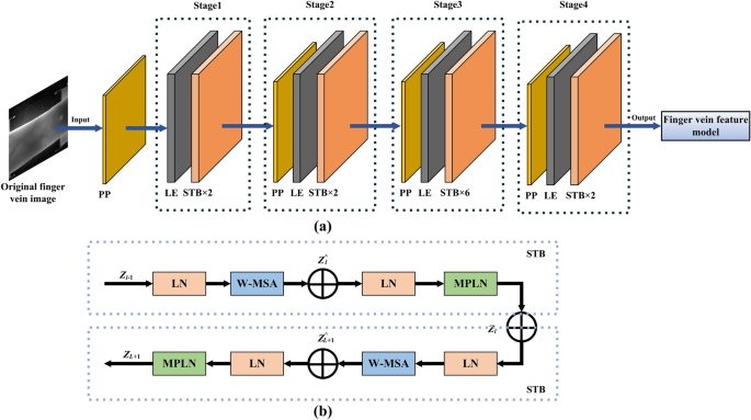
Framework diagrams of the (a) Swi-Transformer network (Swin-TN), (b) Two successive STBs.
-
(ii)
Quantum matrix generation based on quantum walk system: Firstly, The finger vein hash data extraction technology is used to extract the hash value SH of \(Z(x,y)\), which is stored in the encryption user database, and four groups of quantum initial values \({\text{SH}}_{n}^{1} ,{\text{SH}}_{n}^{2} ,{\text{SH}}_{n}^{3} ,{\text{SH}}_{n}^{4} (n = 1,2,3,4)\) are generated by utilizing quantum initial value mapping for SH, which can be can be expressed as follows:
$$\left\{ \begin{gathered} {\text{SH}}_{n}^{1} = \frac{1}{{1 + e^{{\left| {\sin (Dec({\text{SH))}}} \right|^{n} }} }} \times 10^{3} (n = 1,2,3,4) \hfill \\ {\text{SH}}_{n}^{2} = \frac{1}{{\left| {1 + \sin (Dec({\text{SH}})} \right|^{n + 1} }} \times 10^{3} (n = 1,2,3,4) \hfill \\ {\text{SH}}_{n}^{3} = \frac{{\pi^{2} }}{{\pi + \left| {\arctan (Dec({\text{SH)}}^{n} )} \right|}}(n = 1,2,3,4) \hfill \\ {\text{SH}}_{n}^{3} = \frac{{\pi^{{}} }}{{\left| {1 + \cos (Dec({\text{SH}})} \right|^{n + 1} }}(n = 1,2,3,4) \hfill \\ \end{gathered} \right.$$(2)where \(Dec()\) represent the decimal operation. Next, the trajectories of the four walkers are respectively constrained by the corresponding quantum initial values, where \({\text{SH}}_{n}^{1}\) is used to constrain the walking range of the walker, and the constrained walking range of the walker in the 2D rectangular coordinate system \((\xi ,\eta )\) is denoted as \(D_{n} = \{ \left. {(\xi ,\eta )} \right| - {\text{SH}}_{n}^{1} \le x \le {\text{SH}}_{n}^{1} , - {\text{SH}}_{n}^{1} \le y \le {\text{SH}}_{n}^{1} \}\); \({\text{SH}}_{n}^{2}\) is used to constrain the number of steps of the walker; \({\text{SH}}_{n}^{3}\) is used to constrain the initial state of the coin \(\hat{H}_{c,n} = \cos {\text{SH}}_{n}^{3} \left| 0 \right. + \sin {\text{SH}}_{n}^{3} \left| 1 \right.(n = 1,2,3,4)\), and \({\text{SH}}_{n}^{4}\) is used to constrain the coin operator \(\hat{C}_{n} (n = 1,2,3,4)\), and the constrained \(\hat{C}_{n} (n = 1,2,3,4)\) can be expressed as follows:
$$\hat{C}_{n} = \left( {\begin{array}{*{20}l} {\cos {\text{SH}}_{n}^{4} } & {\sin {\text{SH}}_{n}^{4} } \\ {\sin {\text{SH}}_{n}^{4} } & { - \cos {\text{SH}}_{n}^{4} } \\ \end{array} } \right)$$(3)

Secondly, the walker is controlled to walk \({\text{SH}}_{n}^{2}\) steps in range \(D_{n} (n = 1,2,3,4)\), and each walker needs to use the adjustment to the coin state \(\hat{C}_{n} (n = 1,2,3,4)\) before each step. Therefore, the walker each step can be represented by the unitary operator \(\hat{U}_{n} (n = 1,2,3,4)\) as follows:
where \(\otimes\) and \(H\) represent the tensor operation and identity operators in the unitary operator, respectively. \(\hat{S}_{\xi ,n}\) and \(\hat{S}_{\eta ,n}\) represent the displacement operators of the n-th walker in the \(\xi\)-direction and \(\eta\)-direction of the 2D rectangular coordinate system (\(n = 1,2,3,4\)), and their mathematical expression is:
where mod is the mod operation;\(|\xi ,\tau ,0\rangle\) and \(|\xi ,\tau ,1\rangle\) denote the state vectors of the walker after \(\tau\) steps in the positive and negative directions of \(\xi\), respectively; \(|\xi ,\eta ,0\rangle\) and \(|\eta ,\tau ,1\rangle\) denote the state vectors of the walker after \(\tau\) steps in the positive and negative directions of \(\eta\), respectively; \(\langle \xi ,\eta ,0|\) and \(\langle \xi ,\eta ,1|)\) represent the conjugates of the state vectors \(|\xi ,\eta ,0\rangle\) and \(|\xi ,\eta ,1\rangle\). Therefore, the probability matrix \(P_{n} (X,Y,{\text{SH}}_{n}^{2} )\) of the n-th (\(n = 1,2,3,4\)) walker reach the 2D space (X,Y) after \({\text{SH}}_{n}^{2}\) steps can be expressed as31,32:
where \((\widehat{U})^{{{\text{SH}}_{n}^{2} }}\) and \(\left| \psi \right\rangle_{0,n}\) represent the unitary operator after the walker has moved \({\text{SH}}_{n}^{2}\) steps and initial quantum system state. Finally, probability matrix \(P_{n} (X,Y,{\text{SH}}_{n}^{2} )(n = 1,2,3,4)\) is arranged as a 2D matrix respectively, and then the normalization operation is performed, so that the finger vein quantum encryption DNA mask (\({\text{VQEM}}\)), finger vein quantum DNA encryption scrambling index(\({\text{VQEI}}\)), the first finger vein quantum phase mask (\({\text{VQPM}}_{{1}}\)) and the second finger vein quantum phase mask (\({\text{VQPM}}_{2}\)) required in the next encryption step are obtained.
S2: Encryption watermark image generation based on DNA coding and DWT: The framework diagram of the encryption step S2 is also show in Fig. 1b and this step can be divided into two sub-steps:
-
(i)
Color image encryption based on DNA coding: Firstly, the “red” channel data \(P_{R} (x,y)\), “green” channel data \(P_{G} (x,y)\) and “blue” channel data \(P_{B} (x,y)\) are obtained by channel separation operation on the color plaintext image \(P(x,y)\). Subsequently, the DNA encoding operation is performed on \({\text{VQEM}}\), \({\text{VQEI}}\), and each channel’s data of the color plaintext image respectively, thus the coding results \(P_{RD} (\alpha ,\beta )\),\(P_{GD} (\alpha ,\beta )\),\(P_{BD} (\alpha ,\beta )\),\({\text{VQDM}}_{D}\) and \({\text{VQEI}}_{D}\) are obtained. Next, this the \(P_{RD} (\alpha ,\beta )\),\(P_{GD} (\alpha ,\beta )\),\(P_{BD} (\alpha ,\beta )\) executed XOR operation respectively with \({\text{VQDM}}_{D}\) and scrambling operation with \({\text{VQEI}}_{D}\), so that the DNA encoding scrambling results \(P_{RE} (\alpha ,\beta )\), \(P_{GE} (\alpha ,\beta )\), \(P_{BE} (\alpha ,\beta )\) is obtained separately, which can be expressed as follows:
$$\left\{ \begin{gathered} P_{RE} (\alpha ,\beta ) = {\text{SO(}}xor{(}P_{RD} (\alpha ,\beta ),{\text{VQEM}}_{D} ),{\text{VQEI}}_{D} {)} \hfill \\ P_{GE} (\alpha ,\beta ) = {\text{SO(}}xor{(}P_{GD} (\alpha ,\beta ),{\text{VQEM}}_{D} ),{\text{VQEI}}_{D} ) \hfill \\ P_{BE} (\alpha ,\beta ) = {\text{SO(}}xor{(}P_{BD} (\alpha ,\beta ),{\text{VQEM}}_{D} ),{\text{VQEI}}_{D} ) \hfill \\ \end{gathered} \right.$$(7)where \(xor{(}{\text{)}}\) and \({\text{SO(}}{)}\) represent the operations of Xor and scrambling, respectively. Finally, \(P_{RE} (\alpha ,\beta )\), \(P_{GE} (\alpha ,\beta )\) and \(P_{BE} (\alpha ,\beta )\) are performed DNA decoding operation respectively, thus the results of the DNA encoding encryption \(P_{RR} (x,y)\),\(P_{GR} (x,y)\), and \(P_{GR} (x,y)\) is obtained.
-
(ii)
Encryption watermark image generation based on DWT: Firstly, the carrier image \(W(x,y)\) is decomposed into four sub-band images \(LL(x,y)\),\(LH(x,y)\),\(HL(x,y)\) and \(HH(x,y)\) through DWT. Subsequently, \(LH(x,y)\),\(HL(x,y)\) and \(HH(x,y)\) are replaced by \(P_{RR} (x,y)\), \(P_{GR} (x,y)\), and \(P_{GR} (x,y)\) respectively, and the replaced results is performed inverse discrete wavelet transform (IDWT) so that the encryption watermark image \(W_{E} (x,y)\) is obtained, which can be expressed as:
$$\begin{aligned} W_{E} (x,y) & = {\text{IDWT(DWT(}}W(x,y){)} \leftrightarrow (P_{RR} (x,y),P_{RG} (x,y),P_{RB} (x,y))) \\ & = {\text{IDWT}}((LL(x,y),LH(x,y),HL(x,y),HH(x,y)) \leftrightarrow (P_{RR} (x,y),P_{RG} (x,y),P_{RB} (x,y))) \\ \end{aligned}$$(8)where \({\text{DWT}}()\), \({\text{IDWT}}()\) and \(\leftrightarrow\) represent the discrete wavelet transform, inverse discrete wavelet transform and replacement operation, respectively.
S3: Image encryption based on DRPE and ODHE with phase-modulated reference light: The framework diagram of the encryption step S3 is also depicted in Fig. 1b, and the schematic diagram of optical path for DRPE and ODHE with phase-modulated reference light is depicted in Fig. 3, in order to assertively describe the encryption step S3, this step can be divided into two sub-steps:

Schematic diagram of optical path for the DRPE and ODHE with phase-modulated reference light, where P, OL, PH, CL, BS, L, M, PBS and HWP represent polarizer, objective lens, pinhole, collimating lens, beam splitter, lens, mirror, polarization beam splitter, and half-wave plate, respectively.
-
(i)
Encryption object light wave generation based on DRPE in Fresnel ___domain: The encryption watermark image \(W_{E} (x,y)\) is executed image encryption operation based on DRPE in the in Fresnel ___domain with the first finger vein quantum phase mask \({\text{VQPM}}_{{1}}\), the second finger vein quantum phase mask \({\text{VQPM}}_{2}\), a wavelength key (\(\lambda\)) and three diffraction distance keys (\(Z_{1} ,Z_{1} ,Z_{3}\)) so that the encryption object light wave \(G_{o} (u,v)\) is obtained, which can be expressed as:
$$G_{o} (u,v) = {\text{FrT}}_{{\lambda ,{\rm Z}_{3} }} {\text{(FrT}}_{{\lambda ,{\rm Z}_{2} }} {\text{(FrT}}_{{\lambda ,{\rm Z}_{1} }} {(}W_{E} (x,y)){)} \times {\text{VQPM}}_{{1}} {)} \times {\text{VQPM}}_{2} {)}$$(9)where \({\text{FrT}}_{\lambda ,Z} (\cdot)\) represent the Fresnel diffraction operation with wavelength \(\lambda\) and distance \(Z\).
-
(ii)
Holographic ciphertext generation base on ODHE with reference light modulation: In this sub-step, the structured phase mask (SPM) required for modulating the reference light wave is generated by the encryption user through a set of optical parameter keys and can be expressed as:
$${\text{SPM = }}\exp \left( {j\left( {\arg \left( {\exp \left( { - j\frac{\pi }{\lambda f}r^{2} } \right)} \right) + \arg (\exp (ip\varpi ))} \right)} \right)$$(10)where \(\arg (\cdot)\), \(\exp (\cdot)\), are represent the operation of phase extraction and exponential, respectively. \(r\), \(f\) are respectively the radius and the focal length of Fresnel zone plate, \(p\), \(\varpi\) and \(j\) are respectively the topological charge number, the spatial attitude angle of radial Hilbert mask, and imaginary unit, respectively. Next, the reference light wave \(G_{r} (u,v)\) is performed a phase modulation operation with SPM, thus the encryption reference light \(G_{re} (u,v)\) is obtained. Next, the off-axis digital holographic encoding technique (DOHE) is employed to make \(G_{o} (u,v)\) and \(G_{re} (u,v)\) interfere, so that the ciphertext hologram \(I(x,y)\) is generated, which can be expressed as follows:
$$\begin{aligned} I(x,y) & = {\text{ODHE}}({\text{ZP(}}G_{o} (u,v){),}G_{re} (u,v)) \\ & = \left| {{\text{FrT}}_{\lambda ,Z} {\text{(ZP}}(G_{o} (u,v))) + G_{r} (u,v) \times \exp (j{\text{SPM}})} \right|^{2} \\ \end{aligned}$$(11)where \({\text{ZP}}(\cdot)\) and \({\text{ODHE}}(\cdot)\) are represent the operation of zero-padding and off-axis digital holographic encoding, respectively. It should be noted that during the ODHE process, the light intensities \(I_{o} (x,y)\) and \(I_{r} (x,y)\) of \(G_{o} (u,v)\) and \(G_{re} (u,v)\) are recorded respectively for use in the decryption process.
Decryption process
The decryption process in accord with the proposed color image encryption method based on finger vein key and off-axis digital holography with phase-modulated reference light can be divided into three steps: J1: Finger vein authentication and decryption keys acquisition based on Swin-TN, J2: Decryption watermark image reconstruction based on off-axis digital holographic reconstruction (ODHR) with phase-modulated reference light and double random phase decoding (DRPD), J3: Decryption watermark image extraction based on DNA decoding and DWT. Next, each decryption step is described in detail with the help of the corresponding framework diagram. Firstly, the framework diagram of the decryption steps J1 is shown in Fig. 4a.

Framework diagrams of (a) the decryption step J1, (b) the decryption steps J2-J3.
J1: Finger vein authentication and decryption keys acquisition based on Swin-TN: this step can be divided into three sub-steps:
-
(i)
Decryption data acquisition based on finger vein authentication: Firstly, infrared cameras is used to capture finger vein image \(Z^{\dag } (x,y)\) of the decryption use. Subsequently, the finger vein feature model \(\phi_{Z}\) from the encryption database is loaded into the Swin-TN. Next, the prediction model of the Swin-TN is utilized to calculate the prediction result between the \(Z^{\dag } (x,y)\) and \(\phi_{Z}\), which can be expressed as follows:
$$VS = {\text{Softmax(Swin - TN(}}\phi_{Z} ,Z^{\dag } (x,y){))}$$(12)when there is only one encryption user and one decryption user, the softmax function in Eq. 12 can be rewritten as follows:
$$VS = \frac{1}{{1 + e^{Z} }}$$(13)where \(Z\) represent the prediction result output of the prediction model of the Swin-TN between the decryption finger vein and the encryption finger vein. Next, finger vein authentication is performed by determining whether vein similarity (VS) is greater than the preset threshold \(\delta\). If VS is greater than \(\delta\), authentication succeeds and the SH of the encryption the user’s finger vein image, which is stored in the encryption database, is outputted as the decryption data, and then the next decryption sub-step will begin; otherwise, authentication fails, and decryption terminates.
-
(ii)
Decryption keys generation based on quantum initial value mapping and quantum walk system: Firstly, similar to the sub-step (iii) in the encryption step S1, the quantum initial value mapping is again used to generate four sets quantum initial values \({\text{SH}}_{n}^{1} ,{\text{SH}}_{n}^{2} ,{\text{SH}}_{n}^{3} ,{\text{SH}}_{n}^{4} (n = 1,2,3,4)\) for \({\text{SH}}\). Subsequently this four sets quantum initial values are respectively utilized as the input of the quantum walk system, the output results are arranged into 2D matrices and normalized to acquire the correct decryption key for next decryption step, which include the finger vein quantum DNA decryption mask (\({\text{VQDM}}\)), finger vein quantum DNA decryption index(\({\text{VQDI}}\)), first finger vein quantum conjugate phase mask (\({\text{VQPM}}_{1}^{*}\)), and second finger vein quantum conjugate phase mask (\({\text{VQPM}}_{2}^{*}\))
J2: Decryption watermark image reconstruction based on ODHR with phase-modulated reference light and DRPD in Fresnel inverse transform: The framework diagram of the decryption step J2 is shown in Fig. 4b, and this step can be divided into three sub-steps:
-
(i)
Direct current (DC) component elimination based on intensity subtraction method: The \(I_{o} (x,y)\) and \(I_{r} (x,y)\), which is from the encryption database are subtracted from the ciphertext hologram to obtain the DC component elimination result \(I^{\diamondsuit } (x,y)\) of \(I(x,y)\), which can be represented as follows33:
$$I^{\diamondsuit } (x,y) = I(x,y) - I_{o} (x,y) - I_{r} (x,y)$$(14) -
(ii)
decryption object light wave reconstruction based on ODHR with phase-modulated reference light: Firstly, a correct set of optical parameter keys must be inputted into the system by the decryption user, and subsequently, the same operation as in the sub-step (iii) within the encryption step S2 is performed by the system to obtain the decryption structured phase mask \({\text{SPM}}^{\dag }\). Next, the reference light wave is performed a phase modulation operation with \({\text{SPM}}^{\dag }\),thus the decryption reference light between \(G_{rd} (u,v)\) is obtained. Later, \(I^{\diamondsuit } (x,y)\) is multiplied by \(G_{rd} (u,v)\) and the product result is performed a Fresnel inverse diffraction operation with wavelength \(\lambda\) and diffraction distance \(Z\), so that the spectrum distribution containing the decryption object light wave \(G_{o}^{\dag } (u,v)\) is obtained. Finally, the optical information mask \(OIM\) is constructed by the system, and OIM is employed to conduct a filtering operation on this spectral distribution, thus the decryption object light wave \(G_{o}^{\dag } (u,v)\) is obtained, which can be represented as follows:
$$\begin{aligned} G_{o}^{\dag } (u,v) & = {\text{IFrT}}_{{\lambda ,{\text{Z}}}} (I^{\diamondsuit } (x,y) \times G_{rd} (u,v)) \times OIM \\ & = {\text{IFrT}}_{{\lambda ,{\text{Z}}}} (I^{\diamondsuit } (x,y) \times (G_{r} (u,v) \times \exp (j \times {\text{SPM}}^{\dag } ))) \times OIM \\ \end{aligned}$$(15)where \({\text{IFrT}}_{\lambda ,Z} (\cdot)\) represents the operation of inverse Fresnel diffraction with wavelength \(\lambda\) and distance \(Z\).
-
(iii)
Decryption watermark image reconstruction based on DRPD in Fresnel ___domain: the decryption object light wave \(G_{o}^{\dag } (u,v)\) is executed double random phase decoding (DRPD) in Fresnel ___domain with the first finger vein quantum conjugate phase mask \({\text{VQPM}}_{1}^{*}\), the second finger vein quantum conjugate phase mask \({\text{VQPM}}_{2}^{*}\), a wavelength key (\(\lambda\)) and three diffraction distance keys (\(Z_{1} ,Z_{2} ,Z_{3}\)), so that the decryption watermark image \(W_{D} (x,y)\) is obtained, which can be expressed as:
$$W_{D} (x,y) = {\text{IFrT}}_{{\lambda ,{\text{Z}}_{1} }} {\text{(IFrT}}_{{\lambda ,{\text{Z}}_{2} }} {\text{(IFrT}}_{{\lambda ,{\text{Z}}_{3} }} {(}G_{o}^{\dag } {(}u,v{))} \times {\text{VQPM}}_{2}^{*} {))} \times {\text{VQPM}}_{2}^{*} )$$(16)
J3: decryption watermark image extraction based on DNA decoding and DWT: The framework diagram of the decryption step J3 is also shown in Fig. 4b, and this step can be divided into two sub-steps:
-
(i)
decrypted data extraction based on DWT: The decrypted data \(P_{RR}^{\dag } (x,y)\),\(P_{GR}^{\dag } (x,y)\) and \(P_{BR}^{\dag } (x,y)\) are extracted from \(W_{D} (x,y)\) through data extraction technology based on the DWT , and this process can be expressed as:
$$(LL_{D} ,P_{RR}^{\dag } (x,y),P_{GR}^{\dag } (x,y),P_{GB}^{\dag } (x,y)) = {\text{DWT(}}W_{D} (x,y){)}$$(17) -
(ii)
Decrypted result acquisition based on DNA decoding: firstly, the DNA encoding operation is performed on \(P_{RR}^{\dag } (x,y)\),\(P_{GR}^{\dag } (x,y)\),\(P_{BR}^{\dag } (x,y)\), VQDM and VQDI respectively, thereby, the binary encoding results \(P_{RE}^{\dag } (\alpha ,\beta )\),\(P_{GE}^{\dag } (\alpha ,\beta )\),\(P_{BE}^{\dag } (\alpha ,\beta )\),\({\text{VQDM}}_{D}\),\({\text{VQEI}}_{D}\) are obtained. Next, the inverse scrambling operation and XOR operation with \({\text{VQEI}}_{D}\) and \({\text{VQDM}}_{D}\) are performed on \(P_{RE}^{\dag } (\alpha ,\beta )\), \(P_{GE}^{\dag } (\alpha ,\beta )\), \(P_{BE}^{\dag } (\alpha ,\beta )\), so that the XOR decoding results of “red” channel, “green” channel and “blue” channel (\(P_{RD}^{\dag } (\alpha ,\beta )\), \(P_{GD}^{\dag } (\alpha ,\beta )\) and \(P_{BD}^{\dag } (\alpha ,\beta )\)) are obtained respectively, which can be expressed as follows:
$$\left\{ \begin{gathered} P_{RD}^{\dag } (\alpha ,\beta ) = xor{\text{(ISO(}}P_{RE}^{\dag } (\alpha ,\beta ),{\text{VQDI}}_{D} {)},{\text{VQDM}}_{D} {)} \hfill \\ P_{GD}^{\dag } (\alpha ,\beta ) = xor{\text{(ISO(}}P_{GE}^{\dag } (\alpha ,\beta ),{\text{VQDI}}_{D} {)},{\text{VQDM}}_{D} ) \hfill \\ P_{BD}^{\dag } (\alpha ,\beta ) = xor{\text{(ISO(}}P_{BE}^{\dag } (\alpha ,\beta ),{\text{VQDI}}_{D} {)},{\text{VQDM}}_{D} ) \hfill \\ \end{gathered} \right.$$(18)where \({\text{ISO}} (\cdot)\) represents the inverse scrambling operation. Then, \(P_{R}^{\dag } (x,y)\),\(P_{G}^{\dag } (x,y)\) and \(P_{B}^{\dag } (x,y)\) are acquired through the DNA inverse coding operation on \(P_{RD}^{\dag } (\alpha ,\beta )\),\(P_{GD}^{\dag } (\alpha ,\beta )\) and \(P_{BD}^{\dag } (\alpha ,\beta )\) respectively. Finally, \(P_{R}^{\dag } (x,y)\), \(P_{G}^{\dag } (x,y)\) and \(P_{B}^{\dag } (x,y)\) are performed channel merge operation, thus the color decrypted result \(P_{{}}^{\dag } (x,y)\) is obtained.
Simulations and results
In order to demonstrate the feasibility of the proposed color image encryption method, a series of computational simulations were conducted using Python. Firstly, the color image of “Peppers” with the pixel number of \(256 \times 256\) and the pixel pitch of \(8um\) is selected from the USC-SIPI image databases34 as the original color plaintext image \(P(x,y)\) to be encrypted, as shown in Fig. 5a. Secondly, the grayscale of “red”, “green” and “blue” channels corresponding to the color plaintext image is shown in Fig. 5(b1)–(b3), respectively. Afterwards, the 1000 finger vein images from the SDU-MLA vein image database35 are input into the SWIN-TN for finger vein feature extraction, thus the finger vein features model \(\phi_{Z}\) is obtained. Additionally, the encryption user’s finger vein image is also selected from the SDU-MLA and shown in Fig. 5c and its decimal hash value SH is obtained, and the quantum initial value mapping is used to generate four sets of quantum initial values for SH(\({\text{SH}}_{{1}}^{{1}} { = 320}\), \({\text{SH}}_{{1}}^{{2}} { = 390}\), \({\text{SH}}_{{1}}^{{3}} {{ = \pi }}/10\), \({\text{SH}}_{{1}}^{4} {{ = \pi }}/13\); \({\text{SH}}_{2}^{{1}} { = 430}\), \({\text{SH}}_{2}^{{2}} { = 380}\), \({\text{SH}}_{2}^{{3}} {{ = \pi }}/12\), \({\text{SH}}_{2}^{4} {{ = \pi }}/14\); \({\text{SH}}_{3}^{{1}} { = 450}\), \({\text{SH}}_{3}^{{2}} { = 420}\), \({\text{SH}}_{3}^{{3}} {{ = \pi }}/11\), \({\text{SH}}_{3}^{4} {{ = \pi }}/9\); \({\text{SH}}_{4}^{{1}} { = 470}\), \({\text{SH}}_{4}^{{2}} { = 450}\), \({\text{SH}}_{4}^{{3}} {{ = \pi }}/8\), \({\text{SH}}_{4}^{{3}} {{ = \pi }}/8\), \({\text{SH}}_{4}^{4} {{ = \pi }}/10\)). Then, the quantum matrix generation program is employed with these quantum initial values to generate the encryption mask for the subsequent encryption step, including the \({\text{VQEM}}\),\({\text{VQEI}}\), \({\text{VQPM}}_{{1}}\), and \({\text{VQPM}}_{2}\), which are depicted in Fig. 5(d1)–(d4), respectively. Next, the DNA coding encryption results of the “red”, “green” and “blue” channel data (\(P_{RR} (x,y)\), \(P_{GR} (x,y)\), and \(P_{BR} (x,y)\)) of \(P(x,y)\) are obtained using \({\text{VQEM}}\) and \({\text{VQEI}}\), which are respectively presented in Fig. 5(e1)–(e3). Then, the watermark embedding technology based on the DWT is utilized to embed \(P_{RR} (x,y)\), \(P_{GR} (x,y)\), and \(P_{BR} (x,y)\) into the carrier image \(W(x,y)\) as depicted in Fig. 5f, thereby obtaining the encryption watermark image \(W_{E} (x,y)\) as shown in Fig. 5g. Next, \(W(x,y)\) is executed image encryption operation based on DRPE in the Fresnel transform ___domain with the phase keys (\({\text{VQPM}}_{{1}}\),\({\text{VQPM}}_{2}\)) and a set digital keys (\(\lambda = 632.8nm,Z_{1} = 100mm,Z_{2} = 120mm,Z_{3} = 150mm\)) so that the encryption object light wave \(G_{o} (u,v)\) is obtained, whose amplitude and phase are presented in Fig. 5(h1)–(h2), respectively. In addition, the focal length \(r\) and topological charge number \(p\) in the SPM are respectively set as30 mm and 6 such that the phase distribution of the SPM composed of the Fresnel zone plate and the radial Hilbert mask is calculated accordingly by Eq. (12), which is displayed in Fig. 5i. Finally, the reference light \(G_{r} (u,v)\) is phase modulated through SPM to acquire the encrypted reference light \(G_{re} (u,v)\), and the ODHE with Fresnel diffraction distance \(Z = 1500mm\) is employed to interfere between \(G_{re} (u,v)\) and \(G_{o} (u,v)\) for obtaining the holographic ciphertext \(I(x,y)\), which is displayed in Fig. 5j.

(a1) Original color plaintext images “Peppers”; (b1)-(b3) grayscale image information of “red”, “green” and “blue” channels respectively corresponding to the (a1); (c) encryption finger vein image of encryption user; (d1)-(d4) \({\text{VQDM}}\), \({\text{VQEI}}\), and VQPMs of the encryption user (\({\text{VQPM}}_{{1}}\) and \({\text{VQPM}}_{2}\)); (e1)-(e3) encryption results \(P_{RR} (x,y)\),\(P_{GR} (x,y)\), and \(P_{BR} (x,y)\) of (b1)-(b3) by DNA encoding encryption with VQDM and VQEI; (f) carrier image \(W(x,y)\); (g) watermarked image \(W_{E} (x,y)\) of embedding (e1)-(e3) into the \(W(x,y)\); (h1)-(h2) amplitude and phase of the encryption object light \(G_{o} (u,v)\); (i) SPM created by the encryption user; (j) holographic ciphertext \(I(x,y)\).
Subsequently, the decryption process is executed to examine the validity of security keys. The necessary keys for the process of decryption include the finger vein key of the decryption user, the set of digital keys (three diffraction distance keys, the wavelength key, focal length key and topological charge number key).when all decryption keys are correct, the decrypted results of the “red”, “green” and “blue” of the color image (“Peppers’’) are shown in Fig. 6(a1)–(a3), respectively, and the final decrypted color result are shown in Fig. 6b.

(a1)–(a3) Decrypted results of the “red”, “green” and “blue” channels of the color image (“Peppers’’) when all decryption keys are correct, respectively. (b) final decrypted color result when all decryption keys are correct.
From the decrypted results as Fig. 6, as can be seen that the original color plaintext images can be correctly reconstructed with high quality when all decryption keys are correct.
Sensitivity of digital keys analysis
Next, the sensitivity of digital keys is analyzed, where the correlation coefficient (CC) is used as an evaluation function to quantitatively evaluate the similarity between the decrypted image and the original plaintext image. To demonstrate digital key sensitivity in the proposed encryption method, where the digital keys include the three diffraction distance keys, wavelength key, focal length key and topological charge number key. Figure 9 show the relationship between the CC of each channels and the deviation of each digital key, that is, the sensitivity curve of each digital key, where the sensitivity curves of the first diffraction distance key \(Z_{1}\), second diffraction distance key \(Z_{2}\), third diffraction distance key \(Z_{3}\), wavelength key \(\lambda\), focal length key \(f\),and topological charge number key \(p\),are shown in Fig. 7(a)–(f), respectively. In addition, the decrypted results of each channels and the final decrypted results when the first diffraction distance key deviation \(\Delta Z_{1} = - 1mm\), second diffraction distance key deviation \(\Delta Z_{2} = - 1mm\), third diffraction distance key deviation \(\Delta Z_{3} = - 1mm\), wavelength key deviation \(\Delta \lambda = - 1nm\), focal length key deviation \(\Delta f = - 1mm\), and topological charge number key deviation \(\Delta p = - 1\) are also shown in Fig. 7(a)–(f) respectively. It can be seen from Fig. 9 that the correct original plaintext image can only be obtained when all digital keys in the decryption process are correct. When there is even a minor deviation in any digital key, the CC value of each channel sharply declines to 0, causing the decrypted result to resemble random noise, and the original color plaintext image cannot be reconstructed, thus it can be demonstrated that the digital key in the encryption method possesses strong sensitivity.

Sensitivity curves of (a) first diffraction distance key deviation \(Z_{1}\), (b) second diffraction distance key deviation \(Z_{2}\), (c) third diffraction distance key deviation \(Z_{3}\), (d) wavelength key \(\lambda\), (e) focal length key \(f\), and (f) topological charge number key \(p\).
Security of finger vein key analysis
Furthermore, the security of finger vein key is analyzed. The decryption results corresponding to the correct finger vein key and the wrong finger vein key are shown in Fig. 10, and it is notable that the displayed incorrect finger vein images were randomly gathered from over 500 distinct attackers in SDU-MLA. It can be observed from Fig. 8 that when the decryption user’s finger vein key is incorrect, the finger vein similarity (VS) between the wrong finger vein key and the correct finger vein key is lower than the preset threshold (0.75), resulting in the termination of decryption. This proves that the finger vein key in the proposed encryption method possesses strong security.

Tested results about the security of the finger vein key.
Robustness of finger vein key analysis
Moreover, the robustness of finger vein key, including translation robustness, rotation robustness, and illumination robustness, is tested in detail. Firstly, the ability of the finger vein key against translation attack is tested by translating a part of the pixels of the correct finger vein key of the decryption user, and the tested results is shown in Fig. 9a. From the results shown in Fig. 9a, it can be seen that although the finger vein similarity between decryption finger vein key and encryption finger vein key gradually decreases with the increment of the shifted distance of decryption finger vein key, the finger vein similarity corresponding to the finger vein key with 60 pix shifted distance is still higher than the preset threshold (0.75), thus high quality and correctly decrypted image are obtained, which demonstrates that the finger vein key possesses excellent robustness against translation attack. Secondly, the ability of finger vein key to against rotation attack is tested by rotating correct finger vein key of decryption user with different rotation angles, and the tested results is shown in Fig. 9b. From the results shown in Fig. 9b, It is observable that although the finger vein similarity between decryption finger vein key and encryption finger vein key gradually decreases with the increment of the rotated angle of decryption finger vein key, the finger vein similarity corresponding to the finger vein key with 90° rotated angle is still higher than the preset threshold (0.75), thus high quality and correctly decrypted image are obtained, which demonstrates that the finger vein key possesses excellent robustness against rotation attack. Thirdly, the ability of finger vein key to against illumination attack is tested by changing the illumination offset, and the tested results is shown in Fig. 9c. From the results shown in Fig. 9c, It is observable that although the finger vein similarity between decryption finger vein key and encryption finger vein key gradually decreases with the increment of the illumination offset value, the finger vein similarity corresponding to the finger vein key with illumination offset value \(\rho = 40\) is still higher than the preset threshold (0.75), thus high quality and correctly decrypted image are obtained, which demonstrates that the finger vein key possesses excellent robustness against illumination attack.

Tested results about the robustness of finger vein key against (a) translation attack, (b) rotation attack, and (c) Illumination attack.
Noise attack analysis
The robustness of the ciphertext in the face of Gaussian noise and occlusion attacks is also tested. These tests were conducted to assess the vulnerability of the ciphertext to interference from Gaussian noise with mean 0 and standard deviation 0.1 and partial occlusion that could occur during the storage and transmission of the ciphertext. Figure 10a–e show the correct decrypted images of the color plaintext (“Peppers”) under different Gaussian noise intensities \(\upsilon\): 0.2, 0.4, 0.6, 0.8, and 1.0, respectively. Specifically, ciphertext contaminated by Gaussian noise with a specific intensity can be mathematically expressed as:
where \(I(x,y)\) is the holographic ciphertext, \(I^{\prime}(x,y)\) is the contaminated ciphertext, \(N(x,y)\) is the Gaussian noise with mean 0 and standard deviation 0.1, and the coefficient \(\upsilon\) is the noise intensity.

Tested results about the robustness of the ciphertext against Gaussian noise attack. Decrypted results image from contaminated ciphertexts by Gaussian noises with different noise strengths \(\upsilon\): (a) \(\upsilon = 0.2\); (b) \(\upsilon = 0.4\); (c) \(\upsilon = 0.6\); (d) \(\upsilon = 0.8\); (e) \(\upsilon = 1.0\).
In addition, we conducted robustness tests on the “red”, “green” and “blue” channels of the correct decrypted images of the color plaintext (“Peppers”) under different Gaussian noise intensities, including BER (Bit Error Rates), SSIM (Structural Similarity Index), MSE (Mean Squared Error), CC (Correlation Coefficients) and histograms, with the test results as shown in Fig. 11.

BER, SSIM, MSE,CC values and histograms of correct decrypted results under subjected to different Gaussian noise intensities.
where the calculation methods of BER, SSIM, MSE, and CC, can be expressed as follows:
where \(P_{\chi }^{\dag } (x,y)\) and \(P_{\chi } (x,y)\) respectively represent the grayscale values of original plaintext image and the decrypted result at coordinate \((x,y)\) in \(\chi = R,G,B\) channels, \(\overline{{P_{\chi } }}\) and \(\overline{{P_{\chi }^{\dag } }}\) respectively represent the pixel grayscale mean values of the original plaintext image and the decrypted result in \(\chi = R,G,B\) channels. \(xor\) represent the Xor operation. Through the analysis of Figs. 10 and 11, it is evident that the quality of the decrypted image deteriorates as the intensity of Gaussian noise increases. However, the majority of the valid information within the original color plaintext image information remains intact. even when the ciphertext image is attacked by Gaussian noise of maximum intensity. Thus, it can be inferred that the proposed color image encryption method demonstrates a considerably high level of robustness against noise attacks.
Occlusion attack analysis
Next, the robustness of the ciphertext against occlusion attacks is evaluated by partially cropping its pixels. Figure 12(a1) displays the ciphertext with 25% occlusion in a square, while the corresponding decrypted plaintext image are shown in Fig. 12(a2). Figure 12(b1) displays the ciphertext with 25% occlusion in a square, while the corresponding decrypted plaintext image are shown in Fig. 12(b2). Similarly, Fig. 12(c1) displays the ciphertext with 25% occlusion in a rectangle, while the corresponding decrypted plaintext image are shown in Fig. 12(c2). Figure 12(d1) displays the ciphertext with 50% occlusion in a rectangle, while the corresponding decrypted plaintext image are shown in Fig. 12(d2).

Tested results about the robustness of the ciphertext against occlusion attack. Ciphertexts with (a1) 25% occlusion in a square, (b1) 50% occlusion in a square, (c1) 25% occlusion in a rectangle, (d1) 50% occlusion in a rectangle; (a2)–(d2) decrypted result image from (a1)–(d1), respectively.
Moreover, the robustness tests on the “red”, “green” and “blue” channels of the correct decrypted images of the color plaintext (“Peppers”) under different occlusion ranges, including BER, SSIM (Structural Similarity Index), MSE (Mean Squared Error), CC (Correlation Coefficients) and histograms, with the test results as shown in Fig. 13.

BER, SSIM, MSE, CC values and histograms of correct decrypted results under subjected to different occlusion ranges.
Through the analysis of Figs. 12 and 13, it is strikingly obvious that the quality of the decrypted image deteriorates as the occluded area of the ciphertext expands. Nevertheless, the majority of the valid information within the original plaintext image information remains intact even when the ciphertext image suffers a 50% occlusion attack. Consequently, it can be inferred that the proposed color image encryption method demonstrates a considerably high level of robustness against occlusion attack.
Statistical attack analysis
Afterwards to further prove the security of the proposed encryption methods, statistical attacks on histogram analysis and correlation are conducted. Figure 14(a1) and (a3) present the original color plaintext image (“Peppers”) and histograms of the “red”, “green” and “blue” channels of the “Peppers”, respectively. Additionally, Fig. 14(a2) and (a4) display the holographic ciphertext corresponding to the “Peppers” and histograms of this holographic ciphertext. Furthermore, other original plaintext image (“Mandrill”) is also selected from the USC-SIPI image databases and encrypted into separate holographic ciphertext using the proposed color image encryption method, which shown in Fig. 14(b1) and (b2), respectively. Figure 14(b3) display the histograms of the “red”, “green” and “blue” channels of the original color plaintext image (“Mandrill”), while Fig. 14(b4) display the histograms of the ciphertext corresponding to the “Mandrill”. By comparing the histograms presented in Fig. 14(a3)–(b4) with those depicted in Fig. 14(b3)–(b4), it is conspicuously clear that notwithstanding the new original image plaintext (“Mandrill”) being completely different from the previous original image plaintexts (“Peppers”) in terms of the histogram characteristics of the “red”, “green” and “blue” channels, there is no significant disparity between the histograms of the new holographic ciphertext and the previous holographic ciphertext. This observation indicates that the histograms fail to disclose any distinctive characteristics of the original image plaintext. Consequently, it can be concluded that the proposed color image encryption method exhibits extraordinary resilience against histogram attacks.

(a1) original color plaintext image (“Peppers”), (b1) original color plaintext image (“Mandrill”), (a2) and (b2) the holographic ciphertext corresponding to (a1) and (b1); (a3) and (b3) the histograms of (a1) and (a2), (a4) and (b4) the histograms of (a2) and (b2).
Additionally, correlation analysis is also conducted, where 3000 pairs of adjacent pixels in the horizontal, vertical and diagonal directions are randomly chosen from the “red”, “green” and “blue” channels of original image plaintexts (“Peppers”) respectively, for the purpose of calculating the correlation coefficients. Figure 15(a1)–(a3) respectively illustrates the horizontal, vertical, and diagonal correlations of adjacent pixels in the “red” channel of the original image plaintext (“Peppers”). Similarly, Fig. 15(b1)–(b3) respectively illustrate the horizontal, vertical, and diagonal correlations of adjacent pixels in the “green” channel of the original image plaintext (“Peppers”), Fig. 15(c1)–(c3) respectively illustrate the horizontal, vertical, and diagonal correlations of adjacent pixels in the “blue” channel of the original image plaintext (“Peppers”), and Fig. 15(d1)–(d3) respectively illustrate the horizontal, vertical, and diagonal correlations of adjacent pixels in the holographic ciphertext corresponding to the original color image plaintext (“Peppers”). Through the analysis of Fig. 15, it becomes evident that the color image plaintext exhibits strong correlations in all directions in “red”, “green” and “blue” channels, whereas the ciphertext demonstrates weak correlations in all directions. Therefore, the proposed color image encryption method can effectively disrupt the data correlations in the “red”, “green” and “blue” channels of the original color plaintext image, preventing unauthorized attackers from accessing the plaintext image through correlation analysis.

Correlation distributions of (a1)–(a3) in the horizontal direction, diagonal direction, and horizontal direction, respectively, in the “red” channel of the color plaintext (“Peppers”) shown in Fig. 5(b1); (b1)–(b3) in the horizontal direction, diagonal direction, and horizontal direction, respectively, in the “green” channel of the color plaintext (“Peppers”) shown in Fig. 5(b2); (c1)–(c3) in the horizontal direction, diagonal direction, and horizontal direction, respectively, in the “blue” channel of the color plaintext (“Peppers”) shown in Fig. 5(b3); (d1)–(d3) in the horizontal direction, diagonal direction, and horizontal direction, respectively, in the ciphertext shown in Fig. 5j.
Running time analysis
The runtime required for different color plaintexts during the encryption and decryption process is also analyzed. Table 1 lists the used parameters in the simulation and the adopted configuration of the computing platform. In addition, Fig. 16 shows the required running time of different plaintext images in the encryption and decryption process.

The running time of different plaintext images in the encryption and decryption process.
From Fig. 16, it can be seen that although there are small fluctuations in the time required for the encryption process and decryption process of different color plaintext images, but is still controlled within an acceptable range. Therefore, the simulation test can prove that the proposed encryption method has the advantage of fast encryption speed and fast decryption speed.
Additionally, in order to further show the advantages of the proposed encryption method. Table 2 presents the results of the comparison between three recently reported color optical image encryption methods based on biometric keys, and our proposed method. It can be seen from Table 2 that the proposed encryption method has obvious advantages over other color image encryption methods based on biological key, such as large key space, small number of ciphertexts, non-contact authentication of biological key and strong robustness.
Special attack analysis
Finally, the performance of the security system against special attacks is also discussed. Firstly, from the perspective of cryptographic security evaluation, if a system can resist known plaintext attack (KPA), chosen plaintext attack (CPA), and ciphertext-only Attack (COA), and chosen cipher-text attacks (CCA), it can be considered to have sufficient security. Among them, COA poses the most powerful threat to symmetric encryption systems whose ciphertexts are hologram type. However, in the proposed color image encryption method, even if a COA attacker fully understands the encryption and decryption process, they must still accurately recover the structured light phase mask (SPM) in the reference optical path before they can reconstruct the decryption object wave using iterative phase retrieval techniques, extract the decryption watermark image, and ultimately obtain the original plaintext image. It is worth noting that, thanks to the high sensitivity of the SPM to initial optical parameters, unauthorized attackers find it difficult to accurately recover the SPM. To verify this conclusion, we designed the following experiment: assuming the attacker has stolen the ciphertext image and employs a genetic algorithm for 10,00 iterations to recover the SPM, followed by 500 iterations of the Hybrid Input–Output (HIO) phase retrieval algorithm36 to reconstruct the decryption watermark image, and finally utilizes the correct VQDM and VQEI to complete the decryption process. The reconstructed decryption watermark image and the decrypted result are shown in Fig. 17a, b, respectively. As can be seen from Fig. 17, even if attackers steal the correct VQDM and VQDI, the decrypted watermark image and the decrypted result still cannot be accurately recovered. Therefore, it can be demonstrated that the proposed encryption method can effectively resist COA attacks by unauthorized users.

The results of COA. (a) the reconstructed decryption watermark image, (b) the decrypted result.
Discussion and conclusions
In this paper, we propose a color image encryption method based on finger vein key and off-axis digital holography with phase-modulated reference light. In the encryption process of the proposed method, the color plaintext image is first subjected to channel separation, thus the “red”, “green”, and “blue” channel data of the color plaintext image is obtained. Thereafter, the grayscale data of each channel is performed DNA encoding encryption operation with the \({\text{VQEM}}\) and \({\text{VQEI}}\) of the encryption user finger vein, and these encrypted results are embedded into carrier image and encryption watermark image is obtained. Afterwards, the watermark image is performed operations of DRPE and ODHE with \({\text{VQPM}}_{1}\) and \({\text{VQPM}}_{2}\) of encryption user finger vein so that the finally ciphertext hologram is generated. It is worth noting that the diffraction distance of the Fresnel transforms, and the optical parameters used to generate the \({\text{SPM}}\) in DRPE and ODHE with phase-modulated reference light are employed as additional digital key sets, so that the security of the system is significantly strengthened; furthermore, the ciphertext generated by ODHE is amplitude ciphertext with real-value distribution, which has obvious advantages of easy storage and portability. In the decryption process of the proposed method, the decryption user must first authenticate the decryption finger vein key. If the authentication is successful, the additional digital keys also has to be input by the decryption user so that the correct decrypted color image can be obtained; otherwise, authentication fails, and decryption process is terminated.
Moreover, the security of the finger vein key and digital keys is adequately demonstrated, and it can be concluded that the proposed encryption method has a high level of security with large key space and high digital key sensitivity. Additionally, the robustness of the finger vein key is tested through translation attack, rotation attack and illumination attack tested, and the tested results show that the finger vein key authentication algorithm in the proposed color image encryption method exhibits strong robustness against translation attack, rotation attack and illumination attack. Finally, the advantages of the proposed encryption method can be summarized as follows:
-
(1)
Low Key Complexity: In the proposed encryption method, the finger vein key is easy to carry, the digital key is easy to remember, and no phase mask key, so that the complexity of the key can be effectively reduced.
-
(2)
Finger vein key has high security and robustness: In the decryption step of the proposed encryption method, thanks to the finger vein authentication technology based on the Swin-Transformer network (Swin-TN) is used to authenticate the encryption user and the decryption user, thus the security and robustness of finger vein key can be improved.
-
(3)
Large Key Space: In the encryption step of the proposed encryption method, the wavelength and diffraction distance in the double random phase coding process based on Fresnel transform ___domain and the optical parameters of the structured light phase mask (SPM) used in the off-axis digital holography encoding (ODHE) process were set as digital keys, therefore the types and numbers of digital keys are increased, which can effectively improve the security of the encryption system.
-
(4)
Strong storage of ciphertext: In the proposed encryption method, the original plaintext image is finally encoded into an amplitude grayscale ciphertext by ODHE, which is convenient for storage and transportation compared with the traditional complex amplitude ciphertext.
-
(5)
High decryption quality: In the proposed encryption method, the decrypted result has no color distortion, brightness offset, contrast change compared with the original color plaintext image, and the ciphertext has strong resistance to Gaussian noise and occlusion attacks, so as to realize efficient and secure color image encryption.
The promising results of this preliminary study encourage us to continue our research on enhancing the robustness of the finger vein key and the sensitivity of digital keys. Future studies will focus on multi-image encryption technology based on the finger vein key to enhance encryption efficiency and practicality. Additionally, in the subsequent studies, the finger vein key is expected to be introduced into other encryption technologies based on optical principles, such as computational ghost imaging, computer-generated holography, and the iterative phase retrieval algorithm, thereby enhancing the practicability and universality of the finger vein key in optical encryption method. Besides, other biometric features such as voiceprint, 3D face, and iris will also be utilized as the keys of the optical image encryption method in the following research work, thereby accelerating the practical process of the optical image encryption method.
References
Javidi, B. et al. Roadmap on optical security. J. Opt. 18, 083001 (2016).
Liu, S., Guo, C. & Sheridan, J. T. A review of optical image encryption techniques. Opt. Laser Tech. 57, 327–342 (2014).
Hazer, A. & Yıldırım, R. A review of single and multiple optical image encryption techniques. J. Opt. 23, 113501 (2021).
Mehra, I., Singh, K., Agarwal, A. K., Gopinathan, U. & Nishchal, N. K. Encrypting digital hologram of three-dimensional object using diffractive imaging. J. Opt. 17, 035707 (2015).
Refregier, P. & Javidi, B. Optical image encryption based on input plane and Fourier plane random encoding. Opt. Lett. 20, 767–769 (1995).
Sui, L. & Gao, B. Color image encryption based on gyrator transform and Arnold transform. Opt. Laser Tech. 48, 530–538 (2013).
Farah, M. A. B., Guesmi, R., Kachouri, A. & Samet, M. A novel chaos based optical image encryption using fractional Fourier transform and DNA sequence operation. Opt. Laser Tech. 121, 105777 (2020).
Shao, Z. et al. Double color image encryption using iterative phase retrieval algorithm in quaternion gyrator ___domain. Opt. Express 22, 4932–4943 (2014).
Annaby, M. H., Rushdi, M. A. & Nehary, E. A. Color image encryption using random transforms, phase retrieval, chaotic maps, and diffusion. Opt Laser Eng. 103, 9–23 (2018).
Wu, J., Shen, Y. & Xu, G. Integrating Fresnel diffraction, multi-phase retrieval, and hyperchaos mapping for color image encryption. Appl. Opt. 62(844–860), 478668 (2023).
Chen, H., Tanougast, C., Liu, Z. & Sieler, L. Asymmetric optical cryptosystem for color image based on equal modulus decomposition in gyrator transform domains. Opt Laser Eng. 93, 1–8 (2017).
Chen, H., Liu, Z., Zhu, L., Tanougast, C. & Blondel, W. Asymmetric color cryptosystem using chaotic Ushiki map and equal modulus decomposition in fractional Fourier transform domains. Opt Laser Eng. 112, 7–15 (2019).
Zhu, Z., Chen, X.-D., Wu, C., Wang, J. & Wang, W. An asymmetric color-image cryptosystem based on spiral phase transformation and equal modulus decomposition. Opt. Laser Tech. 126, 106106 (2020).
Chen, W., Chen, X. & Sheppard, C. J. R. Optical color-image encryption and synthesis using coherent diffractive imaging in the Fresnel ___domain. Opt. Express 20, 3853–3865 (2012).
Qin, Y., Wang, Z., Pan, Q. & Gong, Q. Optical color-image encryption in the diffractive-imaging scheme. Opt Laser Eng. 77, 191–202 (2016).
He, X., Tao, H., Liu, C. & Zhu, J. Single-shot color image encryption based on mixed state diffractive imaging. Opt Laser Eng. 107, 112–118 (2018).
Qu, G. et al. Optical color image encryption based on Hadamard single-pixel imaging and Arnold transformation. Opt Laser Eng. 137, 106392 (2021).
Qu, G. et al. Optical color watermarking based on single-pixel imaging and singular value decomposition in invariant wavelet ___domain. Opt Laser Eng. 137, 106376 (2021).
Bai, X. et al. Real single-channel color image encryption method based on computational ghost imaging. Laser Phys. Lett. 19, 125204 (2022).
Aziz, G. et al. Photo-isomerization enabled reversible wavelength switching in fiber random laser for color image encryption. Opt. Express. 32, 30380–30392 (2024).
Zhang, C. et al. Simple optical encryption and decryption strategy based on bilayer soft actuator and laser-induced structural color. Opt. Lett. 48, 1562–1565 (2023).
Yan, J., Guo, J., Qu, K. & Li, R.-Z. Two-dimensional transmissive structural colors for high-security information encryption. Appl. Opt. 63, 1340–1346 (2024).
Zhang, Y., He, Y., Li, P. & Wang, X.-Y. A new color image encryption scheme based on 2DNLCML system and genetic operations. Opt Laser Eng. 128, 106040 (2020).
Su, Y., Xu, W., Zhao, J., Chen, L. & Tian, X. Optical color image encryption based on chaotic fingerprint phase mask in various domains and comparative analysis. Appl. Opt. 59, 474–483 (2020).
Su, Y., Xu, W., Li, T., Zhao, J. & Liu, S. Optical color image encryption based on fingerprint key and phase-shifting digital holography. Opt Laser Eng. 140, 106550 (2021).
Wang, Y. et al. Optical single-channel color image encryption based on chaotic fingerprint phase mask and diffractive imaging. Appl. Opt. 62, 1009–1018 (2023).
Abuturab, M. R. & Alfalou, A. Multiple color image fusion, compression, and encryption using compressive sensing, chaotic-biometric keys, and optical fractional Fourier transform. Opt. Laser Tech. 151, 108071 (2022).
Abuturab, M. R. Optical single-channel security system using 3D-logistic map biometric keys for multiple color images. Opt. Quant Electron. 55, 242 (2023).
Abuturab, M. R. Multiple color image cryptosystem based on coupled-logistic-map-biometric keys, QR decomposition with column pivoting and optical Fresnel transform. Opt. Laser Tech. 161, 109109 (2023).
Liu, Z. et al. Swin transformer: Hierarchical vision transformer using shifted windows. In Proceedings of the IEEE/CVF International Conference on Computer Vision. 10012–10022 (2021).
Baryshnikov, Y., Brady, W., Bressler, A. & Pemantle, R. Two-dimensional quantum random walk. J. Stat. Phys. 142, 78–107 (2011).
Abd-El-Atty, B., Iliyasu, A. M., Alanezi, A. & Abd El-latif, A. A. Optical image encryption based on quantum walks. Opt Laser Eng. 138, 106403 (2021).
Demoli, N., Mes̆trović, J. & Sović, I. Subtraction digital holography. Appl. Opt. 42, 798–804 (2003).
“Original images”, http://sipi.usc.edu/database/database.php.
Yin, Y., Liu, L. & Sun, X. SDUMLA-HMT: A multimodal biometric database. In Proceeding 6th Chinese Conference Biometric Recognition. 260–268 (2011).
Chang, X., Yan, A. & Zhang, H. Ciphertext-only attack on optical scanning cryptography. Opt Laser Eng. 126, 105901 (2020).
Acknowledgements
This work is supported by the Natural Science Foundation of Zhejiang Province (LQ22F050005, LY22F040002), Fundamental Research Funds for the Provincial Universities of Zhejiang (2022YW53), National Natural Science Foundation of China (NSFC) (62104219), Natural Science Basic Research Program of Shaanxi (Program No. 2024JC-YBMS-536).
Author information
Authors and Affiliations
Contributions
Boyu Wang: Software, Writing—original draft. Yanfeng Su: Conceptualization, Writing—review & editing. Ming Gao: Supervision. Hong Lyu: Investigation. JiayinZhang: Investigation. Bei Zhou: Visualization. Wenqi Zhong: Investigation. Peng Zhang: Validation. Yinghong Li: Supervision.
Corresponding authors
Ethics declarations
Competing interests
The authors declare no competing interests.
Data availability
Data are available from the corresponding author upon reasonable request.
Additional information
Publisher’s note
Springer Nature remains neutral with regard to jurisdictional claims in published maps and institutional affiliations.
Rights and permissions
Open Access This article is licensed under a Creative Commons Attribution-NonCommercial-NoDerivatives 4.0 International License, which permits any non-commercial use, sharing, distribution and reproduction in any medium or format, as long as you give appropriate credit to the original author(s) and the source, provide a link to the Creative Commons licence, and indicate if you modified the licensed material. You do not have permission under this licence to share adapted material derived from this article or parts of it. The images or other third party material in this article are included in the article’s Creative Commons licence, unless indicated otherwise in a credit line to the material. If material is not included in the article’s Creative Commons licence and your intended use is not permitted by statutory regulation or exceeds the permitted use, you will need to obtain permission directly from the copyright holder. To view a copy of this licence, visit http://creativecommons.org/licenses/by-nc-nd/4.0/.
About this article

Cite this article
Wang, B., Su, Y., Gao, M. et al. Color image encryption based on finger vein key and off-axis digital holography with phase-modulated reference light. Sci Rep 15, 10264 (2025). https://doi.org/10.1038/s41598-025-94320-7
Received:
Accepted:
Published:
DOI: https://doi.org/10.1038/s41598-025-94320-7
