
Abstract
Gastric cancer (GC) is the fifth most common malignant tumor worldwide. Surgical resection remains the primary treatment for GC, with laparoscopic surgery recommended by several international guidelines. Due to complex perigastric vessels, standard D2 lymph node dissection (LND) in laparoscopic GC (LapGC) surgery is challenging. Careful dissection is required to expose, dissect, and ligate vessels without injury, ensuring radical LND. Computer vision has the potential to assist in the identification of key vessels during LapGC surgery, thereby reducing the risk of vascular injury. However, existing publicly available surgical anatomy datasets mainly focus on organ segmentation and simple surgeries. To address the clinical challenges and research needs outlined above, we present the LapGC Key Vascular Anatomy Dataset (LapGC-KVAD-30). This dataset was extracted from thirty complete surgical videos and contains annotations for fifteen types of key vessels across eight D2 LND scenes. The LapGC-KVAD-30 uniquely contains 5303 frames that showcase the dynamic process of key vessels from initial appearance to full exposure (or ligation), providing essential information for effective and safe LND.
Background & Summary
Gastric cancer (GC) has emerged as the fifth most commonly malignant tumor, presenting a significant global health challenge due to its high incidence and mortality1,2. Surgical resection remains the primary treatment for GC. Currently, minimally invasive surgery particularly laparoscopic and robot-assisted surgery have gradually become mainstream in surgical practice which offers several advantages over open surgery: smaller incisions, better surgical vision, less intraoperative blood loss, and more rapid postoperative recovery3,4,5. Notably, laparoscopic GC (LapGC) surgery has been proven by the Chinese Laparoscopic Gastrointestinal Surgery Study (CLASS)3,4,6, the Korean Laparoendoscopic Gastrointestinal Surgery Study (KLASS)7,8,9, and the Japan Clinical Oncology Group study (JCOG)10,11, a series of highquality clinical trials, to have better short-term outcomes and comparable long-term oncological outcomes relative to open surgery, which is recommended by several international treatment guidelines12,13.
According to guidelines, D2 lymph node dissection (LND) is the standard surgical procedure for patients with locally advanced GC, but it presents significant technical challenges, especially because of the complex and numerous perigastric vessels, which makes laparoscopic D2 LND more difficult13,14. The major difficulty of D2 LND lies in identifying the correct vascular sheath layers and dissecting lymphatic and fatty tissues to skeletonize vessels, which can easily result in vascular injuries and intraoperative bleeding15,16,17. A retrospective study has shown that the probability of vascular injury occurrence is 45% due to the intricate anatomy and vascular variations around the stomach18. Also, intraoperative bleeding caused by vascular injuries is one of the most common intraoperative complications19, which might influence the tumor patients’ prognosis severely20. Moreover, a recent study found that nearly 20% of intraoperative adverse events are caused by human visual perception errors in identification including anatomy misidentification21. Therefore, introducing innovative technology is crucial to assist surgeons in rapidly and accurately identifying and locating key vessels, which can effectively reduce the incidence of intraoperative vascular injury complications and enhance surgical safety.
Surgical data science (SDS) aims to optimize surgical outcomes by leveraging advanced data analytics and artificial intelligence (AI), including machine learning (ML), to improve decision-making22,23,24. There is a notably vibrant ___domain within SDS that incorporates the utilization of AI technologies, especially computer vision algorithms for the analysis of minimally invasive surgical videos and the development of AI applications in surgery25. These endeavours aim to furnish surgeons with context-aware intraoperative assistance, ultimately enabling more precise surgical treatment and improving clinical practice25. However, the development of surgical AI applications requires high-quality, publicly available image datasets that contain massive surgical information26, especially anatomical structures27,28. Intraoperative automatic recognition of anatomical structures, which is currently one of the most pivotal research focuses for surgeons, can be utilized for intelligent surgical navigation29 and assistance30, minimizing intraoperative complications risks31, identifying safety zones32, and enhancing surgical education33. At present, the publicly available surgical anatomy datasets with pixel-level segmentation annotations are still limited, which are summarized in Table 127,34,35,36,37,38,39,40,41, such as Dresden Surgical Anatomy Dataset27, LapGyn434, CholeSeg8k35, and Endoscapes41. These datasets have indeed promoted the development of SDS and surgical AI42. However, these existing publicly available surgical anatomy datasets primarily collect images of major organs within the abdominal cavity, covering relatively simple surgical procedures including gallbladder, gynecological, and colorectal surgeries. In particular, they lack detailed anatomical representations of the dynamic exposure, dissection and ligation process of key vessels in complex cancer surgery. Consequently, the generalizability and applicability of the above datasets are still limited for LapGC surgery, which involves more complex surgical scenes and vascular anatomy.
Thus, a key bottleneck currently hindering the development of AI applications in gastric cancer surgeries is the scarcity of high-quality datasets that incorporate detailed anatomical information, particularly concerning vascular structures. To meet this challenge and considering the specific surgical characteristics of D2 LND in GC surgery, this study proposed the LapGC Key Vascular Anatomy Dataset (LapGC-KVAD-30), also referred to as Southern Medical University - Nanfang Hospital - Gastric Cancer - 01 Dataset (SMU-NF-GC-01 Dataset), consisting of 5303 high-resolution frames from 30 complete videos across eight surgical scenes and fifteen types of key vessels, which are detailed in Table 2. The process of construction and annotation of the LapGC-KVAD-30 is illustrated in Fig. 1.

Overview of the Laparoscopic Gastric Cancer Key Vascular Anatomy Dataset. Based on the detailed definition of surgical scenes and key vessels in laparoscopic distal gastrectomy with D2 lymph node dissection, key frames were extracted by expert surgeons. Subsequently, medical annotators performed pixel-level annotations of the key frames under the supervision and guidance of expert surgeons. LapGC-KVAD-30: Laparoscopic Gastric Cancer Key Vascular Anatomy Dataset; SMU-NF-GC-01 Dataset: Southern Medical University-Nanfang Hospital-Gastric Cancer-01 Dataset.
Compared to the publicly available surgical anatomy datasets listed in Table 1, the LapGC-KVAD-30 uniquely annotates the entire dynamic process of the exposure, dissection, or ligation of the key vessels crucial to D2 LND during GC surgery. Aimed at providing a foundational resource for the development of image-guided surgical AI navigation systems for GC, the LapGC-KVAD-30 enables surgeons and researchers to gain a deeper understanding of the anatomical relationships and vascular variations in LapGC surgery. This dataset can contribute to refining surgical planning, simulation training, and intraoperative navigation, ultimately enhancing the precision of LapGC surgeries and potentially improving clinical outcomes.
Methods
Dataset definition
In accordance with the guidelines for the treatment of GC, surgical anatomical characteristics and definition (Supplementary Note 1 and Table S1) of laparoscopic distal gastrectomy (LDG) with D2 LND, we systematically categorized the D2 LND procedure into eight critical scenes (S1–S8)12,13,43. Within these eight unique surgical scenes, the perigastric vessels requiring exposure, dissection, or ligation have been defined as “key vessels”, as detailed in Table 2 and Fig. 2. The temporal dynamic exposure, dissection, and ligation process of each type of key vessel is illustrated in Fig. 3 and as follows:
-
Left gastroepiploic LND (S1): In this scene, the surgeon dissects distally along the splenic vessels to expose the root of the left gastroepiploic artery (LGeA) and the left gastroepiploic vein (LGeV). The exposed vessels are then dissected, clipped, and cut, completing the No.4sb LND. The LGeA and the LGeV typically run in close proximity, with the LGeV generally positioned inferior to the LGeA. Therefore, the LGeA and LGeV (LGeA&V) are defined as accompanying vessels in this study.
-
Greater curvature LND (S2): In this scene, the surgeon cuts the vessels along the greater curvature and dissects the No.4d lymph nodes (LNs). The greater curvature vessels (GCVs) are defined as accompanying vessels, as the arteries and veins run in close proximity.
-
Infrapyloric LND (S3): In this scene, the surgeon exposes the right gastroepiploic vein (RGeV), the anterior superior pancreaticoduodenal vein (ASPDV), and the Accessory right colic vein (ARCV). The RGeV is dissected, clipped, and cut anterior to the APSDV. The surgeon then proceeds upwards to expose and carefully dissect the root of the right gastroepiploic artery (RGeA). Once the RGeA is fully exposed, it is clipped and cut at its root, where it originates from the gastroduodenal artery (GDA). At this point, the dissection of No. 6 LNs is completed.
-
Gastroduodenal artery exposure (S4): In this scene, the surgeon dissects the plane between the posterior wall of the duodenum and the pancreas to expose the GDA. Then, the surgeon dissects from the posterior to the superior wall of the duodenum, guided by the anterior space of the GDA.
-
Suprapyloric LND (S5): In this scene, the surgeon opens the anterior leaf of the hepatoduodenal ligament to expose the roots of the right gastric artery (RGA) and right gastric vein (RGV). The RGA and RGV are then dissected, clipped, and cut. The surgeon continues to dissect along the root of the RGA towards the liver, carefully exposing the anterior and medial walls of the proper hepatic artery (PHA), completing the No. 5 LND.
-
Suprapancreatic LND (S6): In this scene, the surgeon opens the gastropancreatic fold, locates the initial segment of the common hepatic artery (CHA) or splenic artery (SA), and dissects along the perivascular space towards the proximal segment of the celiac trunk. The left gastric artery (LGA) and left gastric vein (LGV) are exposed, dissected, clipped, and cut at their roots. Next, the lymphatic and fatty tissues on the lateral and posterior sides of the LGA are dissected, completing the dissection of the No. 7 and 9 LNs. The surgeon dissects along the superior, anterior, and posterior walls of the SA to complete the No.11p LND. Also, the surgeon dissects the CHA, exposing its anterior and superior walls to complete the No. 8a LND. Notably, during the process of No. 11p LND, the surgical quality control of the KLASS group44,45 standard requires that the splenic vein (SV) should be identified and exposed, or at least exposed the dorsal side of the pancreatic parenchyma. Li et al.46 suggested dissecting the fatty lymphatic tissue along the surface of the SA until near the posterior gastric artery (PGA) to complete No. 11p LND, without specifically requiring the exposure of the SV. In addition, the SV, located posterior to the SA, may exhibit vascular variations, making it occasionally invisible. Therefore, we did not define the SV as a type of key vessel due to the significant individual variability and uncertainty in its exposure during No. 11p LND.
-
No.12a LND (S7): In this scene, the surgeon performs blunt dissection along the potential anatomical space between the medial side of the PHA and the No. 12a LNs, exposing the portal vein (PV) posterior to the PHA. The lymphatic and fatty tissues from the anterior wall of the PV are then dissected, exposing the anterior and left walls of the PV, thus completing the No. 12a LND. Additionally, part of the inferior vena cava (IVC) may also be exposed during No.12a LND. The surgeon clips and cuts the root of the No. 12a LNs anterior to the IVC and PV, to prevent lymphatic leakage and avoid vascular injuries.
-
Lesser curvature LND (S8): In this scene, the surgeon cuts the vessels along the lesser curvature and dissects the No.1 and 3 LNs. The lesser curvature vessels (LCVs) are defined as accompanying vessels, as the arteries and veins run in close proximity.
-
Note: In this study, there are cases that lack certain types of key vessels due to following reasons: (1) vascular variations in patients, resulting in absence of specific key vessels; (2) complex intraoperative conditions (e.g., bleeding, smoke obstruction), which prevented the extraction of frames containing key vessels; (3) technical errors, which resulted in some key vessels not being properly exposed and thus invisible.

Anatomical illustration of surgical scenes and key vessels in laparoscopic distal gastrectomy with D2 lymph node dissection. In this figure, the labels of key vessels are highlighted in bold for emphasis. S1: Left gastroepiploic LND; S2: Greater curvature LND; S3: Infrapyloric LND; S4: Gastroduodenal artery exposure;S5: Suprapyloric LND; S6: Suprapancreatic LND; S7: No.12a LND; S8: Lesser curvature LND. LND: lymph node dissection; LGeA: left gastroepiploic artery; LGeV: left gastroepiploic vein; SA: splenic artery; SV: splenic vein; GCVs: greater curvature vessels; RGeA: right gastroepiploic artery; RGeV: right gastroepiploic vein; ASPDV: anterior superior pancreaticoduodenal vein; ARCV: accessory right colic vein; GCT: gastrocolic trunk; GDA: gastroduodenal artery; CHA: common hepatic artery; PHA: proper hepatic artery; RGA: right gastric artery; RGV: right gastric vein; LHA: left hepatic artery; RHA: right hepatic artery; LGA: left gastric artery; LGV: left gastric vein; PV: portal vein; IVC: inferior vena cava; LCVs: lesser curvature vessels.

The exposure, dissection, and ligation process of key vessels in each scene in laparoscopic distal gastrectomy with D2 lymph node dissection. Each row represents a specific type of key vessel, along with the corresponding surgical steps for exposure, dissection, or ligation. LND: lymph node dissection; LGeA&V: left gastroepiploic artery&vein; GCVs: greater curvature vessels; RGeA: right gastroepiploic artery; RGeV: right gastroepiploic vein; GDA: gastroduodenal artery; PHA: proper hepatic artery; RGA: right gastric artery; RGV: right gastric vein; LGA: left gastric artery; LGV: left gastric vein; CHA: common hepatic artery; SA: splenic artery; PV: portal vein; IVC: inferior vena cava; LCVs: lesser curvature vessels.
Data collection
Considering the time required and workload of frame extraction and annotation, we selected 30 complete LDG videos with D2 LND collected at Nanfang Hospital, Southern Medical University. To ensure the quality of dataset, we excluded low-quality videos, such as those with excessive bleeding, heavy smoke, or blurry clips. Also, this sample size is comparable to publicly available high-quality surgical anatomy datasets (Table 1)27,37,38,40,41. All video data were recorded with laparoscopic cameras from KARL STORZ and saved at a resolution of 1920 × 1080 pixels in MPEG-4 format. All identifiable patient information (e.g., names, ages, or other sensitive data) was anonymized. Also, each video was assigned a simple numeric identifier (ID) (e.g., 1, 2, 3) instead of using any patient-related IDs. This study aims to collect laparoscopic surgery videos and extract surgical images to build a dataset. Therefore, we applied for retrospective and observational ethical approval from the Medical Ethics Committee of Nanfang Hospital, Southern Medical University (Approval Number: NFEC-2023-467). Given the retrospective and observational nature of the study, and since all patient data were anonymized during the research process, the committee waived the requirement for individual patient consent.
Frame extraction
In this study, video frames were manually selected at a constant rate of 25 frames per second (fps) using the FFmpeg framework (www.ffmpeg.org) by three expert surgeons (H.C., Y.H., and J.Y.) who are core members of the CLASS group. The frame selection was based on the complexity of the vascular anatomy, surgical duration, and difficulty of surgical manipulation, resulting in a varying number of frames across different scenes and key vessels. Each frame was saved at a resolution of 1920 × 1080 pixels in PNG format. Frames were selected based on clarity and their temporal sequence to record the dynamic exposure, dissection, and ligation process of key vessels across eight surgical scenes. The following exclusion criteria were applied to frame selection: (1) frames containing any irrelevant operations or extra-abdominal operations; (2) unclear frames containing artifacts, glare, or smoke; (3) blurred or out-of-focus frames. To maintain the authenticity of frames containing vascular structures, no image pre-processing steps (e.g., adjusting image intensity, contrast, or window size) were performed.
Segmentation annotation
The annotation group consisted of three expert surgeons (H.C., Y.H., and J.Y.) with experience in over 300 LapGC surgeries and five medical annotators including a novice surgeon (L.G.) and four medical students (H.W., C.C., B.S., and Y.Q.). The novice surgeon had completed a rotation in the surgical department and participated in over 20 LapGC surgeries. The four medical students are those who have completed undergraduate medical courses including anatomy and surgery, and have watched at least 30 LapGC surgery videos. Strict and standardized training was an essential part and cornerstone of the annotation process47. At first, all members of the annotation group systematically learned how to use the annotation tool LabelMe48. Then, the five medical annotators completed training including learning the process of LDG with D2 LND and identifying each type of key vessel. Finally, we developed a segmentation annotation protocol as a guideline that details the annotation criteria for each type of key vessel across eight different scenes (Supplementary Note 2, Table S2, and Figure S1–S14). Frames from the same video were assigned to a single annotator for pixel-level segmentation annotation. Medical annotators used the polygonal annotation tool in LabelMe to outline the boundaries of the key vessels, adhering strictly to the annotation protocol. Then, the three expert surgeons conducted a thorough review of annotations together to correct any errors, such as misidentification of blood-bearing adipose tissue as key vessels. Annotations not meeting the standards outlined in our annotation protocol were sent back to the medical annotators for re-annotation. Sample annotation frames of each type of key vessel across eight scenes are presented in Fig. 4.

Sample annotation frames for each type of key vessel across eight scenes. The figure displays raw frames (left column) and their corresponding pixel-wise annotated frames (right column) for key vessels in D2 lymph node dissection during laparoscopic distal gastrectomy. LGeA&V: left gastroepiploic artery&vein; GCVs: greater curvature vessels; RGeA: right gastroepiploic artery; RGeV: right gastroepiploic vein; GDA: gastroduodenal artery; PHA: proper hepatic artery; RGA: right gastric artery; RGV: right gastric vein; LGA: left gastric artery; LGV: left gastric vein; CHA: common hepatic artery; SA: splenic artery; PV: portal vein; IVC: inferior vena cava; LCVs: lesser curvature vessels.
Data Records
The LapGC-KVAD-30 is stored at the Science Data Bank (https://doi.org/10.57760/sciencedb.20852)49. This dataset consists of three independent subsets: the training set (20 cases), validation set (5 cases), and test set (5 cases). Each folder corresponds to a single case. All folders within these subsets share the same folder structure, which is illustrated in Fig. 5 and described below:
-
Folders: Each folder is named according to the unique ID number of its corresponding surgical video, ranging from “1” to “30”. Each folder contains 8 subfolders named “S1”, “S2”,…, “S8” and 1 CSV file.
-
Subfolders: Each subfolder corresponds to a specific surgical scene and contains two types of PNG files, which are stored in two separate folders: “frames” and “annotations”. In “frames” folder, the filenames follow a structured format that includes the surgical video ID, scene ID, and the frame sequence number. For example, a filename like “10_S3_25.png” indicates that this file comes from a surgical video whose ID is number 10, specifically from the 25th frame selected from Scene 3 (S3) within this video. The “annotations” folder contains the corresponding segmentation mask files, which are saved in PNG format. Compared to the frame files, each mask file has a “_mask” suffix. For example, the corresponding mask file for “10_S3_25.png” is named “10_S3_25_mask.png”.
-
CSV file: The CSV file provides a detailed record that includes the filenames of the frames, their corresponding mask filenames, the video ID, the scene ID, and the names of the key vessels present.
-
-
Color file: The “color file” is a JSON-format file that stores the names of fifteen types of key vessels, the Red-Green-Blue (RGB) values of their corresponding colors as displayed in the segmentation masks, and the names of their associated scenes.

Dataset folder structure. LapGC-KVAD-30 has three subsets (training, validation, and test) and a file named “color.json”. The training, validation, and test sets contain 20, 5, and 5 folders respectively. Each folder corresponds to a single case and contains eight subfolders, which include frames, segmentation annotations, and a CSV file that stores the names of all files along with their corresponding information. The “color.json” file stores the RGB values of the colors for fifteen types of key vessels. For better understanding, we visualized the “color.json” file as a table and displayed the color corresponding to each RGB value. LapGC-KVAD-30: Laparoscopic Gastric Cancer Key Vascular Anatomy Dataset; SMU-NF-GC-01 Dataset: Southern Medical University-Nanfang Hospital-Gastric Cancer-01 Dataset; RGB: Red-Green-Blue. ID: identifier.
Technical Validation
Dataset characteristics
The distribution of frames across the eight critical surgical scenes in the LapGC-KVAD-30 is visualized in Fig. 6a, with S1 to S8 accounting for 12.60%, 7.98%, 23.49%, 6.56%, 11.79%, 23.61%, 6.75% and 7.22% of the total frames, respectively. Figure 6b shows the frame count at which key vessels appear across these eight critical scenes, providing a thorough visualization that reveals the distribution patterns of different types of key vessels in each scene. Figure 6c illustrates the distribution of these eight scenes across all 30 videos, including the total frame count of each video and the frame count of each scene within the videos. Overall, the distribution of frame count in the LapGC-KVAD-30 varies across the eight critical scenes, with notable differences in both the frame count and distribution patterns of key vessels in each scene. This highlights the complexity of vascular anatomy during the LapGC surgery and the critical importance of constructing a key vascular anatomy dataset. In addition, Fig. 6d showed that the frame proportion of different scenes in the training set, validation set, and test set is similar to that in the entire dataset, indicating that the data separation is appropriate, which is beneficial for future benchmarking.

Visualization of frame count distribution for Laparoscopic Gastric Cancer Key Vascular Anatomy Dataset. (a) The distribution of the 5303 key frames across the eight scenes (S1-S8) in LapGC-KVAD-30. (b) The count of frames for each key vessel across the eight scenes. Vessels are categorized by artery (red), vein (blue), and accompanying vessels (green). (c) The frame count for each of the eight scenes per video. (d) The frame proportion of eight scenes in LapGC-KVAD-30 and its three subsets. LGeA&V: left gastroepiploic artery&vein; GCVs: greater curvature vessels; RGeA: right gastroepiploic artery; RGeV: right gastroepiploic vein; GDA: gastroduodenal artery; PHA: proper hepatic artery; RGA: right gastric artery; RGV: right gastric vein; LGA: left gastric artery; LGV: left gastric vein; CHA: common hepatic artery; SA: splenic artery; PV: portal vein; IVC: inferior vena cava; LCVs: lesser curvature vessels; ID: identifier.
Intra- and inter-annotator consistency
In this study, frames were annotated by five medical annotators and refined by three expert surgeons. Thus, three kinds of consistencies should be evaluated: intra-annotator consistency (same annotator at different times), inter-annotator consistency (medical annotator vs. medical annotator), and inter-annotator consistency (medical annotator vs. expert surgeon). We used these metrics to calculate the three kinds of consistencies27:
-
Dice coefficient (Fig. 7a): The Dice coefficient is a metric that measures the degree of overlap between distinct annotations, ranging from 0 to 1, where 0 indicates no overlap at all, and 1 signifies complete overlap.
Fig. 7 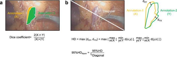
Consistency evaluation metrics. (a) The formula for the Dice coefficient. (b) The formula for the normalized 95% Hausdorff Distance (95%HDnorm). “X” denotes the segmentation annotation of annotator-1, while “Y” refers to the annotation of annotator-2. The symbol “ ∩ ” represents the intersection operation between X and Y. “dXY” refers to the minimum Euclidean distance from a point \(x\in X\) to the set Y. “dYX” refers to the minimum Euclidean distance from a point y \(\,\in Y\) to the set X.
-
The 95th Hausdorff Distance (Fig. 7b): The 95th Hausdorff Distance (95% HD) is a robust distance metric used to evaluate the dissimilarity between a reference annotation and another annotation. It computes the maximum of the directed distances from each point in one set to the nearest point in the other set, taking into account the 95th percentile to reduce the influence of outliers. In this study, we normalize this metric relative to the length of the frame diagonal, masking values within the range of 0 to 1. A value of 0 in the normalized 95%HD (95% HDnorm) denotes perfect correspondence between the annotations (zero separation), while a value of 1 represents the extreme case where the greatest distance between any matched points equals the image diagonal.

A subset containing 100 frames was randomly selected from LapGC-KVAD-30 for consistency evaluation, covering all scenes and key vessel types. The analysis aimed to evaluate the three kinds of consistencies, which were detailed and displayed in Table 3, Table S3 and as follows:
-
For intra-annotator consistency analysis of the same annotator at different times, five medical annotators (L.G., H.W., C.C., Y.Q., and B.S.) from the annotation group were asked to annotate the 100 images twice within one month, with at least one 1-week interval between each annotation. The mean Dice coefficients for different types of vessels varied from 0.93 to 0.97, suggesting high consistency. Additionally, 95% HDnorm values under 0.01 corroborated the strong intra-annotator reliability.
-
For inter-annotator consistency analysis of the medical annotators, the annotation results of five medical annotators (L.G., H.W., C.C., Y.Q., and B.S.) were compared. The mean Dice coefficients exhibited a slight decrease, with values ranging from 0.85 to 0.94, suggesting a satisfactory level of consistency among annotators of the same expertise level. Correspondingly, the 95% HDnorm values between 0.00 and 0.04 also supported this satisfactory consistency.
-
For inter-annotator consistency analysis of medical annotators and the expert surgeon, the expert surgeon (H.C.) annotated the 100 frames for comparison with five annotators (L.G., H.W., C.C., Y.Q., and B.S.). The mean Dice coefficients ranged from 0.84 to 0.93, showing a close alignment between annotators and the expert surgeon, which indicates a consistent annotation approach across different expertise levels after strict training. The 95% HDnorm values, which fell within the range of 0.01 to 0.04, echoed this finding.
In conclusion, the consistency analysis of the subset confirmed that annotations were consistently reliable regardless of the annotator, the time of annotation, and the annotators’ level. This high level of consistency lays a solid foundation for accurate and reproducible segmentation of key vessels. Similarly, the public Dresden surgical anatomy datasets27 reported Dice coefficients ranging from 0.62 to 0.99 when evaluating the annotation consistency between different annotators, which aligns with the results of our study. This underscores the importance of strict annotation training, expert review, and refinement of annotations in the construction of high-quality surgical anatomy datasets.
Advantages and limitations of the dataset
Currently, publicly available surgical anatomy datasets mainly focus on gallbladder, gynecological, and colorectal surgeries27,34,41, with no data available for GC surgery. These datasets typically focus on organs and nearby structures (e.g. liver, pancreas, cystic artery), lacking images showing the manipulation of key vessels during surgery. However, GC surgery is challenging due to the complex anatomy and the numerous perigastric vessels. During D2 LND, it is crucial to dissect, expose, or ligate key vessels in different scenes. This dataset contains images of dynamic manipulation processes of perigastric vessels in LDG with D2 LND, which will help advance AI research in GC surgery and improve surgical safety.
However, this dataset faces several limitations. Firstly, to construct a high-quality dynamic vascular anatomy dataset, we selected surgical videos with minimal bleeding, limited smoke, and clear frames. As a result, the current dataset may exhibit a selection bias based on the clarity of the surgical frames. Secondly, due to the inherent differences in complexity of vascular anatomy, surgical duration of scenes, and the difficulty of surgical manipulations, the number of frames containing key vessels in each scene may be different. Thus, there are class imbalances of surgical scenes and key vessels causing by these differences. However, the class imbalances accurately reflect the the complexity of perigastric vascular anatomy and technical characteristics of D2 LND for GC. Thirdly, the frames in this dataset were recorded using the same type of laparoscopic device at a single center, with a white-light modality. Therefore, the AI models developed based on this dataset may have limited generalization performance when applied to different centers, laparoscopic devices, and imaging modalities. In the future, potential solutions to above limitations include collecting surgical videos with varying levels of clarity and gathering multi-center, multi-device, and multi modality imaging data to increase the diversity of the dataset and reduce selection bias. Especially, data augmentation50 and customized weighted loss functions51 can be applied to address class imbalance and enhance the performance of AI models.
Code availability
All custom code used in the construction of the LapGC-KVAD-30 and technical validation is publicly available at https://github.com/CalvinSMU/LapGC-KVAD-30.
References
Siegel, R. L., Miller, K. D., Wagle, N. S. & Jemal, A. Cancer statistics, 2023. CA Cancer J Clin 73, 17–48 (2023).
Sung, H. et al. Global Cancer Statistics 2020: GLOBOCAN Estimates of Incidence and Mortality Worldwide for 36 Cancers in 185 Countries. CA Cancer J Clin 71, 209–249 (2021).
Yu, J. et al. Effect of Laparoscopic vs Open Distal Gastrectomy on 3-Year Disease-Free Survival in Patients With Locally Advanced Gastric Cancer: The CLASS-01 Randomized Clinical Trial. JAMA 321, 1983–1992 (2019).
Hu, Y. et al. Morbidity and Mortality of Laparoscopic Versus Open D2 Distal Gastrectomy for Advanced Gastric Cancer: A Randomized Controlled Trial. J Clin Oncol 34, 1350–1357 (2016).
Parisi, A. et al. Current status of minimally invasive surgery for gastric cancer: A literature review to highlight studies limits. Int J Surg 17, 34–40 (2015).
Huang, C. et al. Laparoscopic vs Open Distal Gastrectomy for Locally Advanced Gastric Cancer: Five-Year Outcomes From the CLASS-01 Randomized Clinical Trial. JAMA Surg 157, (2022).
Son, S. Y. et al. Laparoscopic vs Open Distal Gastrectomy for Locally Advanced Gastric Cancer: 5-Year Outcomes of the KLASS-02 Randomized Clinical Trial. JAMA Surg 157, 879–886 (2022).
Hyung, W. J. et al. Long-Term Outcomes of Laparoscopic Distal Gastrectomy for Locally Advanced Gastric Cancer: The KLASS-02-RCT Randomized Clinical Trial. J Clin Oncol 38, 3304–3313 (2020).
Lee, H. J. et al. Short-term Outcomes of a Multicenter Randomized Controlled Trial Comparing Laparoscopic Distal Gastrectomy With D2 Lymphadenectomy to Open Distal Gastrectomy for Locally Advanced Gastric Cancer (KLASS-02-RCT). Ann Surg 270, 983–991 (2019).
Katai, H. et al. Short-term surgical outcomes from a phase III study of laparoscopy-assisted versus open distal gastrectomy with nodal dissection for clinical stage IA/IB gastric cancer: Japan Clinical Oncology Group Study JCOG0912. Gastric Cancer 20, 699–708 (2017).
Katai, H. et al. Survival outcomes after laparoscopy-assisted distal gastrectomy versus open distal gastrectomy with nodal dissection for clinical stage IA or IB gastric cancer (JCOG0912): a multicentre, non-inferiority, phase 3 randomised controlled trial. Lancet Gastroenterol Hepatol 5, 142–151 (2020).
Japanese Gastric Cancer Association. Japanese Gastric Cancer Treatment Guidelines 2021 (6th edition). Gastric Cancer 26, (2023).
Ajani, J. A. et al. Gastric Cancer, Version 2.2022, NCCN Clinical Practice Guidelines in Oncology. J Natl Compr Canc Netw 20, 167–192 (2022).
Zhang, X. & Tanigawa, N. Learning curve of laparoscopic surgery for gastric cancer, a laparoscopic distal gastrectomy-based analysis. Surg Endosc 23, 1259–1264 (2009).
Ryu, K. W. et al. Surgical complications and the risk factors of laparoscopy-assisted distal gastrectomy in early gastric cancer. Ann Surg Oncol 15, 1625–1631 (2008).
Tu, R. H. et al. Development of lymph node dissection in laparoscopic gastrectomy: safety and technical tips. Transl Gastroenterol Hepatol 2, 23 (2017).
Lu, J. et al. Factors affecting the quality of laparoscopic D2 lymph node dissection for gastric cancer: a cohort study from two randomized controlled trials. Int J Surg 109, 1249–1256 (2023).
Wu, J. M. et al. Vascular injury and anatomy during laparoscopy - assisted distal gastrectomy with D2 lymphadenectomy for gastric cancer. Chinese Journal of Gastrointestinal Surgery 22, 955–960 (2019).
Liu, Z. Y. et al. Intraoperative Adverse Events, Technical Performance, and Surgical Outcomes in Laparoscopic Radical Surgery for Gastric Cancer: A Pooled Analysis From 2 Randomized Trials. Ann Surg 278, 222–229 (2023).
Liang, Y. X. et al. Impact of intraoperative blood loss on survival after curative resection for gastric cancer. World J Gastroenterol 19, 5542–5550 (2013).
Suliburk, J. W. et al. Analysis of Human Performance Deficiencies Associated With Surgical Adverse Events. JAMA Netw Open 2, e198067 (2019).
Maier-Hein, L. et al. Surgical data science - from concepts toward clinical translation. Med Image Anal 76, 102306 (2022).
Loftus, T. J. et al. Artificial Intelligence and Surgical Decision-making. JAMA Surg 155, 148–158 (2020).
Maier-Hein, L. et al. Surgical data science for next-generation interventions. Nat Biomed Eng 1, 691–696 (2017).
Mascagni, P. et al. Computer vision in surgery: from potential to clinical value. NPJ Digit Med 5, 163 (2022).
Maier-Hein, L. et al. Heidelberg colorectal data set for surgical data science in the sensor operating room. Sci Data 8, 101 (2021).
Carstens, M. et al. The Dresden Surgical Anatomy Dataset for Abdominal Organ Segmentation in Surgical Data Science. Sci Data 10, 3 (2023).
Kolbinger, F. R. et al. Anatomy segmentation in laparoscopic surgery: comparison of machine learning and human expertise - an experimental study. Int J Surg 109, 2962–2974 (2023).
Luo, X., Mori, K. & Peters, T. M. Advanced Endoscopic Navigation: Surgical Big Data, Methodology, and Applications. Annu Rev Biomed Eng 20, 221–251 (2018).
Chadebecq, F., Lovat, L. B. & Stoyanov, D. Artificial intelligence and automation in endoscopy and surgery. Nat Rev Gastroenterol Hepatol 20, 171–182 (2023).
Kitaguchi, D. et al. Real-time vascular anatomical image navigation for laparoscopic surgery: experimental study. Surg Endosc 36, 6105–6112 (2022).
Madani, A. et al. Artificial Intelligence for Intraoperative Guidance: Using Semantic Segmentation to Identify Surgical Anatomy During Laparoscopic Cholecystectomy. Ann Surg 276, 363–369 (2022).
Ward, T. M. et al. Surgical data science and artificial intelligence for surgical education. J Surg Oncol 124, 221–230 (2021).
Leibetseder, A. et al. Lapgyn4: a dataset for 4 automatic content analysis problems in the ___domain of laparoscopic gynecology. In: Proceedings of the 9th ACM Multimedia Systems Conference). Association for Computing Machinery (2018).
Hong, W. Y. et al. Cholecseg8k: a semantic segmentation dataset for laparoscopic cholecystectomy based on cholec80. Preprint at https://arxiv.org/abs/2012.12453 (2020).
HeiSurf HeiChole Surgical Workflow Analysis and Full Scene Segmentation. Synapse https://www.synapse.org/Synapse:syn25101790/wiki/25608802 (2021).
Grammatikopoulou, M. et al. CaDIS: Cataract dataset for surgical RGB-image segmentation. Medical Image Analysis 71, 102053 (2021).
Wang, Z. et al. AutoLaparo: A New Dataset of Integrated Multi-tasks for Image-guided Surgical Automation in Laparoscopic Hysterectomy. In: Medical Image Computing and Computer Assisted Intervention – MICCAI 2022 (eds Wang, L. et al.). Springer Nature Switzerland (2022).
Madad Zadeh, S. et al. SurgAI3.8K: A Labeled Dataset of Gynecologic Organs in Laparoscopy with Application to Automatic Augmented Reality Surgical Guidance. J Minim Invasive Gynecol 30, 397–405 (2023).
Ghamsarian, N. et al. Cataract-1K Dataset for Deep-Learning-Assisted Analysis of Cataract Surgery Videos. Sci Data 11, 373 (2024).
Mascagni, P. et al. Endoscapes, a critical view of safety and surgical scene segmentation dataset for laparoscopic cholecystectomy. Sci Data 12, 331 (2025).
Batić, D., Holm, F., Özsoy, E., Czempiel, T. & Navab, N. EndoViT: pretraining vision transformers on a large collection of endoscopic images. Int J Comput Assist Radiol Surg 19, 1085–1091 (2024).
Song, J. H. et al. Predictive Value of KLASS-02-QC Assessment Score on KLASS-02 Surgical Outcomes: Validation of Surgeon Quality Control and Standardization for D2 Lymphadenectomy. Ann Surg 278, e1011–e1017 (2023).
Han, S. U. et al. Surgeon Quality Control and Standardization of D2 Lymphadenectomy for Gastric Cancer: A Prospective Multicenter Observational Study (KLASS-02-QC). Ann Surg 273, (2021).
Kim, H. I. et al. Standardization of D2 lymphadenectomy and surgical quality control (KLASS-02-QC): a prospective, observational, multicenter study [NCT01283893]. BMC Cancer 14, 209 (2014).
Li, P. et al. Strategy of laparoscopic suprapancreatic lymph node dissection for advanced gastric cancer. Annals of Laparoscopic and Endoscopic Surgery 1, (2016).
Meireles, O. R. et al. SAGES consensus recommendations on an annotation framework for surgical video. Surg Endosc 35, 4918–4929 (2021).
Russell, B. C., Torralba, A., Murphy, K. P. & Freeman, W. T. LabelMe: A Database and Web-Based Tool for Image Annotation. International Journal of Computer Vision 77, 157–173 (2008).
Gou, L. F. et al. Dynamic Key Vascular Anatomy Dataset for D2 Lymph Node Dissection During Laparoscopic Gastric Cancer Surgery. Science Data Bank. https://doi.org/10.57760/sciencedb.20852 (2025).
Wang, Y. et al. Regularizing Deep Networks With Semantic Data Augmentation. IEEE Trans Pattern Anal Mach Intell 44, 3733–3748 (2022).
Fernando, K. R. M. & Tsokos, C. P. Dynamically Weighted Balanced Loss: Class Imbalanced Learning and Confidence Calibration of Deep Neural Networks. IEEE Trans Neural Netw Learn Syst 33, 2940–2951 (2022).
Acknowledgements
This work was financially supported by the Guangdong Basic and Applied Basic Research Foundation (grant no.2021A1515010022), Science and Technology Program of Guangzhou (grant no.2025A04J4017) and Special Funds for the Cultivation of Guangdong College Students’ Scientific and Technological Innovation (grant no.pdjh2024a086). We appreciate the support from the annotation group and surgical teams at Department of General Surgery, Nanfang Hospital, Southern Medical University. Special thanks to Prof. Q.D. and Prof. H.Y. for their significant contributions to this study.
Author information
Authors and Affiliations
Contributions
H.C., Q.D., Y.H., J.Y. and L.G. conceptualized and compiled the dataset, crafted the annotation protocols, orchestrated the annotation process, and wrote the manuscript. H.C., Y.H., J.Y. contributed to the data collection, frame extraction, and refining the dataset through review. L.G., H.W., C.C., B.S. and Y.Q. contributed to the data annotation. J.L. and H.C. contributed to dataset visualization and designed the anatomical atlas sketch. H.W., C.C., and H.Y. executed the technical validation and data statistical analysis. H.Y.W., H.Y. and G.L. reviewed and revised the manuscript. B.Z., X.Y., J.L. and X.B. assisted with compiling and organizing the reference materials and contributed to drafting the annotation protocol. All authors read and approved the final version of the manuscript. L.G., H.W., C.C. and J.L., contributed equally as the co-first authors. H.C., Q.D., Y.H., J.Y. and G.L. contributed equally as the co-corresponding authors.
Corresponding authors
Ethics declarations
Competing interests
The authors declare no competing interests.
Additional information
Publisher’s note Springer Nature remains neutral with regard to jurisdictional claims in published maps and institutional affiliations.
Supplementary information
Rights and permissions
Open Access This article is licensed under a Creative Commons Attribution-NonCommercial-NoDerivatives 4.0 International License, which permits any non-commercial use, sharing, distribution and reproduction in any medium or format, as long as you give appropriate credit to the original author(s) and the source, provide a link to the Creative Commons licence, and indicate if you modified the licensed material. You do not have permission under this licence to share adapted material derived from this article or parts of it. The images or other third party material in this article are included in the article’s Creative Commons licence, unless indicated otherwise in a credit line to the material. If material is not included in the article’s Creative Commons licence and your intended use is not permitted by statutory regulation or exceeds the permitted use, you will need to obtain permission directly from the copyright holder. To view a copy of this licence, visit http://creativecommons.org/licenses/by-nc-nd/4.0/.
About this article

Cite this article
Gou, L., Wu, H., Chen, C. et al. Dynamic key vascular anatomy dataset for D2 lymph node dissection during laparoscopic gastric cancer surgery. Sci Data 12, 903 (2025). https://doi.org/10.1038/s41597-025-05255-7
Received:
Accepted:
Published:
DOI: https://doi.org/10.1038/s41597-025-05255-7
