
Abstract
Traditional aluminum–silicon alloy pistons are gradually replaced by steel pistons, which has become the trend of future diesel engine development. However, the efficient design and broad application of steel pistons are limited by the higher density of steel. For this reason, a new lightweight design method for steel pistons in diesel engines was proposed in this paper. The progressive design of the cooling gallery cross-section and the topology optimization of the window region were carried out to meet the strength and deformation requirements. Ultimately, a lightweight steel piston (LSP) was obtained. The results of the study showed that the total mass of LSP could be reduced by 8.86% compared to the original steel piston (OSP). The thermal states of LSP are all superior to those of OSP. The highest temperature, maximum thermal stress, maximum longitudinal thermal deformation, and maximum transverse thermal deformation can be reduced by 0.96 °C, 3.03%, 11.65%, and 8.99%, respectively. LSP has a larger thermo-mechanical coupling stress manifestation compared to OSP. However, the maximum longitudinal and transverse thermo-mechanical coupling deformations can be obtained with a significant reduction of 8.33% and 42.19%, respectively.
Introduction
The concept of lightweight first originated in motorsports in the nineteenth century. Lightweight is an eternal theme in the field of mechanical design and manufacturing1. With the growing emphasis on energy conservation and emission reduction in the automotive industry worldwide, structural weight reduction is of great significance. Lightweight research has become the technological frontier and hotspot of the automotive industry in this century. Literature2 has shown that a 100 kg reduction in vehicle mass can reduce fuel consumption by about 0.3 to 0.5 L per 100 km, with a corresponding reduction in CO2 emissions of about 1 kg. Although the piston is the core component of the engine, operating in a harsh environment for a long period of time, more than 50% of the heat flow in the cylinder is transferred to the piston3, resulting in the traditional aluminum alloy piston no longer being able to withstand the in-cylinder environment4. The steel piston has gradually become the mainstream of development due to its high-temperature resistance, high-pressure capacity, and wear resistance5. However, the high density of steel materials makes it difficult to solve the problem of lightweight effectively.
Machol6 reduced the mass of steel pistons by reducing wall thickness and optimizing inner wall machining processes. However, during this period, there was a lack of support from computer technology, relying on craft methods and imperfect experimental testing methods, making it challenging to ensure testing accuracy and computational efficiency. With the rapid development of electronic technology, simulation methods have greatly improved the efficiency of lightweight design research. Spangenberg et al.7 proposed that reducing compression height is a universal lightweight design method for steel pistons. Lightweighting can also be achieved by reducing the skirt thickness and introducing weight-reduction slots. Ottliczky et al.8 used monolithic forgings, seam welding technology to connect the piston ring area with the skirt, thin-wall structures, large cooling gallery structures, and low compression height design methods to reduce the weight of steel pistons. Liu et al.9 performed a parametric lightweight design of the head, but the window region was not considered, while the design method was more complex. In addition to the above optimization of structural parameters for steel pistons, topology optimization can more effectively improve the material utilization and change the configuration of the structure, thus genuinely achieving the purpose of lightweight10. Since the concept of continuous structure topological optimization was first introduced by Bendsøe and Kikuchi11 in 1988, topology optimization methods have been developed, such as homogenization method12, level-set method13,14, variable density method15,16, evolutionary structural optimization method17, independent continuous variables and smooth method18, and moving morphable components method19,20, etc. The various methods complement each other to drive the coordinated development of macro/microstructures. Topological optimization is an essential component of engineering structural design with high efficiency and flexibility21 and has gradually been applied to the design of engine pistons. Barbieri et al.22 use products made with topological optimization technology and additive manufacturing to replace aluminum pistons. Gaidur et al.23,24 found that a 1% to 3% reduction in the mass of aluminum alloy pistons after topology optimization can enhance the stress response and maximum displacement while ensuring that the safety factor is in the optimal range. Dalpadulo et al.25 redesigned an aluminum alloy piston based on topology optimization and achieved a 15% weight reduction while maintaining structural rigidity. Badadhe et al.26 reduced the weight of the studied aluminum alloy piston by 10% using a honeycomb structure. The design stress of the honeycomb piston is much lower than the allowable stress. Barbieri et al.27 used topology optimization to define the best structural topology of the steel piston, which is only a 9% increase compared to the original 380 g of the aluminum piston. Du et al.28 applied topology optimization in the piston pin boss region, reducing the mass by 30%. By topology optimization, Lee et al.29 removed the excess material from the piston, reducing the mass by about 5%. Gabriel et al.30 increased the piston life by almost 8 times while reducing the weight by 5% by optimizing the topology structure and improving the connection between the skirt and box wall. Zhao et al.31 optimized three desired regions of the piston with weight as the optimization objective using the variable density method and achieved a weight reduction of 12.5%. Huo et al.32 completed the topology optimization design of the piston using the variable density method, which reduced the mass by approximately 6.471% while selecting the same material. Chen et al.33 proposed a piston lattice structure design method based on reliability topology optimization, which can reduce the mass by 11.8%.
In summary, relatively few studies have been conducted on the lightweight design of steel pistons. Therefore, the purpose of this paper is to propose a new lightweight design method for the steel piston to reduce the weight of the head and skirt regions. Specifically, the progressive method was adopted in the head region to expand the cross-section boundary of the cooling gallery continuously. Topology optimization was adopted in the window region to ensure that the optimized steel piston meets the design requirements of thermo-mechanical coupling strength and skirt deformation. This method is simple in design and can achieve desired weight reduction.
Experiment and simulation
Experimental procedure
A diesel engine equipped with steel pistons was used for the test34. The material is 38MnVS6 for steel pistons35. The specific temperature measurement point locations for the steel piston are shown in Fig. 1. The diameter of each measurement hole is 2 mm, and the shortest distance from the wall is 1.5 mm. The thin wall thickness of the steel piston and, considering the acquisition of more critical temperature measurement points, the measurement points are arranged in a symmetrical distribution with a total of 5. The specific test procedure for the collection of temperature data and the in-cylinder pressure data of the diesel engine can be referred to in the literature9. The data of the diesel engine at the maximum torque condition (400 N·m @ 1600 r/min) was selected for the test as the condition for this study.

The specific temperature measurement point locations for the steel piston.
Simulation model
The simulation model of the temperature field of the steel piston for the studied condition was established based on the third type of thermal boundary conditions36. Accurate thermal boundary conditions9 were obtained by comparing and iteratively correcting the simulation calculations with the experimental results. Further, the gas pressure needs to be loaded while establishing the thermo-mechanical coupling simulation model of the steel piston. The specific gas pressures were loaded to the characteristic regions as shown in Fig. 2. As shown in the figure, the top surface is uniformly distributed with the maximum pressure inside the cylinder, and the remaining characteristic areas are usually empirically assigned as different percentages of the maximum pressure37.

Schematic diagram of gas pressure loading in characteristic regions.
Calibration
To ensure the accuracy of the temperature field simulation model of the steel piston, a verification analysis of the temperature at the measurement points was conducted. The temperature values of the simulation model are shown in Fig. 3., and the comparison between the experimental values and simulation values of 5 measuring points is shown in Table 1. From Fig. 3. and Table 1, the results indicate that the error between the experimental and simulation values of each measurement point is within a reasonable range, and the simulated temperature field distribution meets the accuracy requirements for further research.

The temperature values of the simulation model.
Lightweight design method
Design flow
In this paper, a new lightweight design method for diesel engine steel pistons was proposed, and the complete design flow is shown in Fig. 4.

A new lightweight design flow for diesel engine steel pistons.
Step 1: The original steel piston (OSP) in the UG NX 12.0 software interacted with ANSYS 18.0/Workbench. The steel piston was meshed and imported into the Steady-State-Thermal module to establish the steel piston temperature simulation model. The accuracy of the steel piston temperature simulation model was verified through tests, and accurate thermal boundary conditions were obtained. The validation criterion is a relative error of ≤ 5% between the simulated and tested temperature values of the steel piston. This step has been completed in the sections above.
Step 2: The high-precision temperature simulation model was used for further research and analysis in this step. This step mainly focuses on the lightweight design of the steel piston head region. Specifically, a steel piston model with a large cooling gallery structure was constructed by offsetting the cross-section of the gallery outward. For each large-gallery steel piston model, a temperature simulation model and a thermal stress simulation model were built in the Steady-State-Thermal and Static Structural modules, respectively. Further, a thermo-mechanical coupling simulation model was built in the Static Structural module based on the maximum in-cylinder gas pressure obtained. The strength of steel pistons with extensive galleries was calibrated by combining the stresses of the steel pistons. Finally, the largest volume of the gallery was obtained.
Step 3: The largest volume of the gallery was used for further research and analysis in this step. This step mainly focuses on the lightweight design of the steel piston window region. Specifically, a steel piston topology optimization simulation model was established in the Topology Optimization module of Workbench by setting the design space, design variables, and objective functions for topology optimization. The model was solved iteratively, and the optimized structure was obtained. The topology-optimized geometry needs to be exported to the UG NX 12.0 software for the geometry reconstruction. Then, the temperature simulation model, thermal deformation simulation model, and thermo-mechanical coupling simulation model for the geometrically reconstructed model were established. Further, the overall strength of the steel piston was calibrated in conjunction with the thermo-mechanical coupling stresses. On this basis, the thermal and thermo-mechanical coupling deformations of the skirt were verified. The minimum mass of the window region was obtained while satisfying the above requirements. The lightweight steel piston (LSP) was obtained at this point, and the design was complete.
Design method
The new lightweight design method proposed is mainly aimed at the lightweight of the head and window, and is shown in Fig. 5. The specific design region is shown in Fig. 5a. The details are described below
-
(1)
The head region
Lightweighting in this region is achieved by a cross-section progressive method. A new large cross-section gallery is constructed by setting an outward offset curve based on the original shape. The design boundary is defined by the steel piston boundary. The minimum wall thickness of the head region should not be less than 1 mm is required. During the optimization process, the offset is adjusted by 0.10 mm each time to approach the target value gradually. The advantage of this method is that the process is simple and fast, and it is suitable for size optimization after determining the basic structure or configuration.
Fig. 5 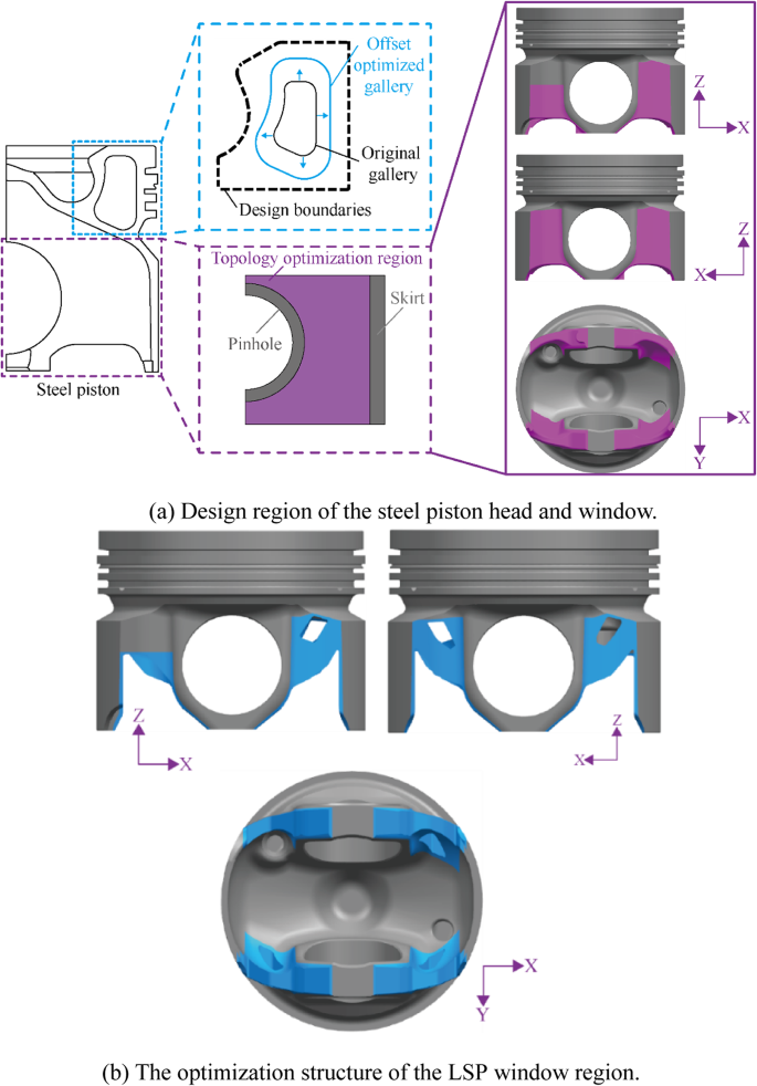
Specific design methods for steel piston head and window regions.
-
(2)
The window region
The topology optimization method aims to find the optimal material layout and force transfer paths in a predefined region with high design freedom38. Among them, the variable density method is widely used in practical engineering applications39. Therefore, the variable density method was used to redesign the window region in this paper. It is assumed that the nonlinear relationship between density and material properties is shown in Eq. (1).
$$\left\{ \begin{aligned}& E = \eta^{a} E{}_{0} \\& \nu = \nu_{0} \end{aligned} \right.$$(1)where E is the Young’s modulus of the material, Pa; ν is the Poisson’s ratio; η is the material density, kg·m−3; α is a constant and > 1. Subscript 0 represents the properties of the actual material used.

The mathematical model of the variable density method is shown in Eq. (2).
where ηi is the relative density of the element, kg·m−3. The parts with a relative density equal to or close to 1 need to be retained, while the parts close to 0 need to be deleted. fi is the volume force, N·m−3; ti is the surface force, N·m−2. M0 is an upper limit for a given initial structural material mass. M* is the mass of material removed specified for optimization. ε is the lower limit density. \(J_{1} , \, J_{2} , \ldots , \, J_{k}\) is the element number with constant unit density after optimization.
As can be seen from the figure, there is a difference in the selection of the four regions optimized for the window to preserve the cooling oil inlet and outlet structure. The thermal loads were neglected in the optimization process because the thermal stresses only constitute a small fraction of the total stress in the design region31. The topology optimization simulation model was loaded with the in-cylinder gas pressure shown in Fig. 2 above. The convergence accuracy of the analysis was set to 0.1%. The topological optimization is carried out with the minimum stiffness of the steel piston under mechanical load as the constraint, aiming for the lightest mass.
The volume of the LSP obtained through optimization is 114,601.3122 mm3, which reduced the mass by 8.86% compared to 125,742.1482 mm3 of the OSP. The LSP gallery is obtained by offsetting the gallery cross-section of the OSP by 0.4 mm to the outside. The volume of the gallery in the head region of the LSP increased from 44,162.5541 mm3 in the OSP to 49,148.2408 mm3 with a corresponding mass reduction of 11.29%. The optimization structure of the LSP window region is shown in Fig. 5b. The volume of the window region of the LSP is decreased from 14,770.2121 mm3 of the OSP to 8585.2136 mm3, with a corresponding mass reduction of 41.87%.
Results and discussions
Thermal state analysis
The thermal state distribution is shown in Fig. 6. Among them, the temperature field distribution of steel pistons is shown in Fig. 6a. The overall temperature distribution of OSP and LSP is consistent. The highest temperatures of the steel pistons are all found at the throat, with OSP and LSP of 446.03 °C and 445.07 °C, respectively. The throat of the LSP is closer to the larger oil cavity, which allows for better cooling by the engine oil, resulting in a highest temperature that is 0.96 °C lower than that of the OSP. The thermal stress distribution of steel pistons is shown in Fig. 6b. The maximum thermal stress for both OSP and LSP also appears in the throat, being 414.94 MPa and 402.35 MPa, respectively. The maximum thermal stress is reduced by 12.59 MPa compared to the OSP, which is a decrease of 3.03%. Since more heat can be dissipated in the LSP, the maximum thermal stress can be reduced by 12.59 MPa, a reduction of 3.03%.

Thermal state distribution of steel pistons.
To describe in more detail, characteristic lines need to be focused on, as shown in Fig. 7. Starting from the center of the combustion bowl, the path along the positive X-axis radial direction in the head is taken as the combustion bowl path studied. Starting from the bottom end of the skirt, the path along the positive Z-axis radial direction is taken as the longitudinal path of the skirt studied. Starting from the middle protrusion of the skirt (at a height of 14 mm), the counterclockwise circumferential path is taken as the transverse path of the skirt studied.

Schematic diagram of the characteristic lines of the steel piston..
The thermal state of the characteristic lines of steel pistons is shown in Fig. 8. Specifically, the temperature and thermal stress of the combustion bowl are shown in Fig. 8a. It shows that the thermal state distribution of the combustion bowl for LSP and OSP is essentially consistent. Further, the comparison of characteristic values of the thermal state of steel pistons is shown in Table 2. According to Fig. 8a and Table 2, the minimum temperatures of LSP and OSP are 237.89 °C and 239.34 °C, respectively, both located at the bottom of the combustion bowl. The highest temperatures of LSP and OSP are 444.97 °C and 445.98 °C, respectively, both located at the throat. However, the thermal stresses are minimal at the combustion bowl center and are 22.76 MPa and 22.93 MPa for LSP and OSP, respectively. The position near the throat region is affected by the geometrical mutation, with LSP and OSP reaching their maximum thermal stress values of 375.26 MPa and 385.28 MPa, respectively. The distribution of longitudinal thermal deformation and transverse thermal deformation of the skirt is shown in Fig. 8b. From the figure, it can be seen that the longitudinal thermal deformation of the bottom end of the skirt is the largest and gradually decreases upward. However, LSP reaches minimum deformation earlier at the top of the skirt than OSP and then rises slowly. The maximum value of LSP is 0.091 mm, which is 11.65% lower than that of OSP with 0.103 mm. The transverse thermal deformations of the skirt are all in the trend of high in the center and low at the sides. The maximum value of the LSP is 8.99% lower at 0.081 mm compared to the OSP of 0.089 mm.
Thermo-mechanical coupling state analysis
The thermo-mechanical coupling stress distribution of steel pistons obtained from the simulation models is shown in Fig. 9. The overall distributions of OSP and LSP are the same. The maximum thermo-mechanical coupling stresses all occur at the transition edge of the second ring groove. The temperature gradient at this ___location is large, and the mesh quality is poor, resulting in a stress concentration phenomenon. The OSP and LSP are 589.15 MPa and 608.16 MPa, respectively. LSP is only 3.23% larger than OSP. Moreover, the steel material studied has high strength, which can meet the actual working requirements. It should be noted that the object of this paper is the steel piston, which has higher strength than the conventional aluminum alloy piston. Therefore, the lightweight design proposed in this paper is only suitable for high-strength piston materials. The head of the steel piston is also subjected to uneven thermo-mechanical coupling stresses. Stress concentrations are also found in the throat. The stresses in the skirt are relatively small, none exceeding 100 MPa.

Thermal state of characteristic lines of steel pistons.
Thermo-mechanical coupling state of characteristic lines of steel pistons is shown in Fig. 10. Specifically, the thermo-mechanical coupling stress of the combustion bowl is shown in Fig. 10a. As shown in Fig. 10a, the thermo-mechanical coupling stress distribution in the combustion bowl of OSP and LSP is consistent. Further, the comparison of characteristic values of the thermo-mechanical coupling state of steel pistons is shown in Table 3. According to Fig. 10a and Table 3, the maximum value is reached in the mutation region of the throat. The OSP and LSP are 418.36 MPa and 429.14 MPa, respectively. LSP generates a thermo-mechanical coupling stress that is 10.78 MPa higher than the OSP due to thinner wall thickness when simultaneously bearing thermal and thermo-mechanical loads. It can be seen from Fig. 10b that both the longitudinal and transverse thermo-mechanical coupling deformations of the LSP are significantly lower than those of the OSP. The maximum longitudinal value of the LSP is 0.066 mm, which is a reduction of 0.006 mm, or 8.33% less, compared to the 0.072 mm of the OSP. The maximum transverse value of the LSP is 0.037 mm, which is reduced by 0.027 mm compared to the 0.064 mm of the OSP, a reduction of 42.19%. From the above, it can be seen that although LSP has larger thermo-mechanical coupling stresses than OSP, the thermo-mechanical coupling deformation obtains a substantial improvement.

Thermo-mechanical coupling stress distribution of steel pistons.

Thermo-mechanical coupling state of characteristic lines of steel pistons.
Conclusions
In this paper, a new lightweight design method was proposed for high-density steel pistons. The asymptotic method of the cross-section of the cooling gallery was adopted for the head region, and topology optimization was adopted for the window region. The ultimate LSP was obtained with strength and deformation that met the requirements. The main findings of the study are as follows.
-
(1)
The lightweight design of the steel piston in this paper results in a reduction of 8.86% in the total mass of the LSP compared to the OSP. In this case, the mass corresponding to the head region of the LSP can be reduced by 11.29%, and the mass corresponding to the window region can be reduced by 41.87%.
-
(2)
Both LSP and OSP experience their highest temperatures and maximum thermal stresses at the throat. The LSP’s throat, being closer to the larger oil cavity, benefits from better cooling by the engine oil, leading to a highest temperature that is 0.96 °C lower than that of the OSP. This improved cooling efficiency also results in a 3.03% reduction in maximum thermal stress for the LSP compared to the OSP. The maximum longitudinal and transverse thermal deformations of the LSP are both smaller than those of the OSP, with reductions of 11.65% and 8.99%, respectively. A lower level of stress and deformation can make steel pistons more reliable during operation, reducing the risk of fatigue damage and failure caused by stress concentration or excessive deformation, thereby improving the performance and longevity of steel pistons in real-world applications.
-
(3)
The overall maximum thermo-mechanical coupling stress for both SP and LSP occurs at the transition edge of the second ring groove. Although LSP has larger thermo-mechanical coupling stresses than OSP, the thermo-mechanical coupling deformation obtains a significant reduction. The maximum longitudinal and transverse thermo-mechanical coupling deformation of LSP can be reduced by 8.33% and 42.19%, respectively, compared to OSP.
Data availability
The datasets generated and/or analysed during the current study are not publicly available due to the data forms part of an ongoing study, but are available from the corresponding author on reasonable request.
Abbreviations
- LSP:
-
Lightweight steel piston
- OSP:
-
Original steel piston
- E :
-
Young’s modulus, Pa
- f i :
-
Volume force, N m−3
- J :
-
Element number
- M*:
-
Mass, Kg
- M 0 :
-
Mass, Kg
- t i :
-
Surface force, N m−2
- α :
-
Constant
- ε :
-
Density, kg/m3
- η :
-
Density, kg/m3
- ν :
-
Poisson’s ratio
References
Zhong, Q. P. et al. On the main technical ways to lightweight mechanical equipment components. J. Mech. Eng. 48(18), 2–6. https://doi.org/10.3901/JME.2012.18.002 (2012).
Fan, Z. J., Gui, L. J. & Su, R. Y. Research and development of automotive lightweight technology. J. Automot. Saf. Energy 5(1), 1–16. https://doi.org/10.3969/j.issn.1674-8484.2014.01.001 (2014).
Apaydin, S. & Doner, N. Effects of piston cooling gallery geometry on temperature and flow in a heavy-duty diesel engine. Thermal Sci. Eng. Prog. 51, 102644. https://doi.org/10.1016/j.tsep.2024.102644 (2024).
Schneider, S. et al. System comparison of steel & aluminium pistons for PC diesel engines. Auto Tech Review 3(10), 24–29. https://doi.org/10.1365/s40112-014-0759-7 (2014).
Shi, X. M. Design of highly-strengthened diesel forged steel piston (Shandong University, 2017).
Machol, M. R. Lightweight reciprocating parts for motors. Transactions (Soc. Automob. Eng.) 8, 269–278. https://doi.org/10.2307/44579027 (1913).
Spangenberg, S. et al. Reduction of mass on piston assemblies. MTZ Worldwide 67(4), 10–12. https://doi.org/10.1007/BF03227834 (2006).
Ottliczky, E. et al. Steel pistons for passenger car diesel engines. MTZ Worldwide eMagazine 72(10), 10–15. https://doi.org/10.1365/s38313-011-0095-0 (2011).
Liu, Y. et al. Research on lightweight design method of diesel engine steel piston based on heat transfer characteristics. Appl. Thermal Eng. 248, 123344. https://doi.org/10.1016/j.applthermaleng.2024.123344 (2024).
Cheng, Z. R., Yan, J. & Peng, Y. D. Lightweight design of solar dish concentrator based on evolutionary structure method. Acta Energiae Solaris Sin. 41(4), 99–106 (2020).
Bendsøe, M. P. & Kikuchi, N. Generating optimal topologies in structural design using a homogenization method. Comput. Methods Appl. Mech. Eng. 71(2), 197–224. https://doi.org/10.1016/0045-7825(88)90086-2 (1988).
Suzuki, K. & Kikuchi, N. A homogenization method for shape and topology optimization. Comput. Methods Appl. Mech. Eng. 93(3), 291–318. https://doi.org/10.1016/0045-7825(91)90245-2 (1991).
Wang, M. Y., Wang, X. & Guo, D. A level set method for structural topology optimization. Comput. Methods Appl. Mech. Eng. 192(1–2), 227–246. https://doi.org/10.1016/S0045-7825(02)00559-5 (2003).
Allaire, G., Jouve, F. & Toader, A. M. Structural optimization using sensitivity analysis and a level-set method. J. Comput. Phys. 194(1), 363–393. https://doi.org/10.1016/j.jcp.2003.09.032 (2004).
Bendsøe, M. P. Optimal shape design as a material distribution problem. Struct. Optim. 1(4), 193–202. https://doi.org/10.1007/BF01650949 (1989).
Sigmund, O. A 99 line topology optimization code written in Matlab. Struct. Multidiscip. Optim. 21(2), 120–127. https://doi.org/10.1007/s001580050176 (2001).
Xie, Y. M. & Steven, G. P. A simple evolutionary procedure for structural optimization. Comput. Struct. 49(5), 885–896. https://doi.org/10.1016/0045-7949(93)90035-C (1993).
Sui, Y. K. & Yang, D. Q. A new method for structural topological optimization based on the concept of independent continuous variables and smooth model. Acta Mech. Sin. 14(2), 179–185. https://doi.org/10.1007/BF02487752 (1998).
Guo, X., Zhang, W. & Zhong, W. Doing topology optimization explicitly and geometrically—A new moving morphable components based framework. J. Appl. Mech. 81(8), 081009. https://doi.org/10.1115/1.4027609 (2014).
Zhang, W. et al. A new topology optimization approach based on Moving Morphable Components (MMC) and the ersatz material model. Struct. Multidiscip. Optim. 53(6), 1243–1260. https://doi.org/10.1007/s00158-015-1372-3 (2016).
Zhou, J. K., Xia, L. J. & Huang, K. Y. Design-oriented topology optimization of structures. J. Ship Mech. 26(4), 538–546. https://doi.org/10.3969/j.issn.1007-7294.2022.04.009 (2022).
Barbieri, S. G. et al. A design strategy based on topology optimization techniques for an additive manufactured high performance engine piston. Procedia Manuf. 11, 641–649. https://doi.org/10.1016/j.promfg.2017.07.162 (2017).
Gaidur, M., Pascal, I., Ciobotar, C. C. et al. Analytical study regarding the topological optimization of an internal combustion engine piston. In IOP Conference Series: Materials Science and Engineering, Vol. 997 (1) 012117 (2020). https://doi.org/10.1088/1757-899X/997/1/012117.
Gaidur, M., Pascal, I., Rakosi, E. et al. Contributions towards improving the displacement and strain responses of an internal combustion engine piston through topology optimization. In IOP Conference Series: Materials Science and Engineering, Vol. 1220(1) 012021 (2022). https://doi.org/10.1088/1757-899X/1220/1/012021.
Dalpadulo, E., Pini, F. & Leali, F. Assessment of computer-aided design tools for topology optimization of additively manufactured automotive components. Appl. Sci. 11(22), 10980. https://doi.org/10.3390/app112210980 (2021).
Badadhe, R. B. & Navthar, R. R. Design and topological optimization of an internal combustion engine piston. Open Access Repos. 10(11), 54–67 (2023).
Barbieri, S. G. et al. Design of an additive manufactured steel piston for a high performance engine: developing of a numerical methodology based on topology optimization techniques. SAE Int. J. Engines 11(6), 1139–1150. https://doi.org/10.4271/2018-01-1385 (2018).
Du, F. R. & Tao, Z. Study on lightweight of the engine piston based on topology optimization. Adv. Mater. Res. 201–203, 1308–1311. https://doi.org/10.4028/www.scientific.net/AMR.201-203.1308 (2011).
Lee, Z. R. & Ku, P. X. Geometry design and optimization of piston by using finite element method. In Journal of Physics: Conference Series, Vol. 2120(1) 012013 (2021). https://doi.org/10.1088/1742-6596/2120/1/012013.
Gabriel, D., Adelmann, J., Hettich, T. et al. Light weight pistons for friction optimized spark ignition engines. In Internal Combustion Engine Division Fall Technical Conference, Vol. 46179, V002T07A007 (2014). https://doi.org/10.1115/ICEF2014-5452.
Zhao, J., Du, F. & Yao, W. Structure analysis and topology optimization of a bent-bar-frame piston based on the variable density approach. In dynamic systems and control conference, Vol. 46193, V002T30A002 (2014). https://doi.org/10.1115/DSCC2014-6118.
Huo, X. D., Zheng, M. J. & Wu, W. J. Light weight analysis of piston based on topology optimization. J. Shijiazhuang Tiedao Univ. (Nat. Sci.) 26(1), 486–493. https://doi.org/10.13319/j.cnki.sjztddxxbzrb.2013.01.022 (2013).
Chen, J. L. et al. Reliability topology optimization design of piston lattice structure for internal combustion engine. J. Mech. Strength 45(1), 91–97. https://doi.org/10.16579/j.issn.1001.9669.2023.01.012 (2023).
Liu, Y. et al. Study on transient thermal state of steel piston in diesel engine under cold start condition. Appl. Thermal Eng. 244, 122744. https://doi.org/10.1016/j.applthermaleng.2024.122744 (2024).
MAHLE GmbH. Pistons and engine testing, Springer Fachmedien Wiesbaden, 2016. ISBN10: 9783658099411.
Liu, Y. et al. Research and analysis of a thermal optimisation design method for aluminium alloy pistons in diesel engines. Case Stud. Thermal Eng. 52, 103667. https://doi.org/10.1016/j.csite.2023.103667 (2023).
Liu, Y. et al. Experimental and simulation study on aluminium alloy piston based on thermal barrier coating. Sci. Rep. 12(1), 10991. https://doi.org/10.1038/s41598-022-15031-x (2022).
Yue, B. et al. Topology optimization of frame mold for autoclave process. Acta Aeronaut. ET Astronaut. Sin. 43(3), 541–553. https://doi.org/10.7527/S1000-6893.2021.25141 (2022).
Ding, M., Geng, D. & Zhou, M. D. topology optimization strategy of structural strength based on variable density method. J. Shanghai Jiaotong Univ. 55(6), 764–773. https://doi.org/10.16183/j.cnki.jsjtu.2019.301 (2019).
Acknowledgements
This work was supported by the Major Science and Technology Projects in Yunnan Province [Grant Nos. 202402AG050009] and the National Natural Science Foundation of China [Grant Nos. 51965027].
Author information
Authors and Affiliations
Contributions
Yang Liu: Methodology, Writing–original draft, Writing–review & editing. Jilin Lei: Funding acquisition, Project administration, Supervision. Jikun Chen: Data curation. Weiwei Gao: Formal analysis. Hu Peng: Formal analysis. Jianrui Wang: Formal analysis.
Corresponding author
Ethics declarations
Competing interests
The authors declare no competing interests.
Additional information
Publisher’s note
Springer Nature remains neutral with regard to jurisdictional claims in published maps and institutional affiliations.
Rights and permissions
Open Access This article is licensed under a Creative Commons Attribution-NonCommercial-NoDerivatives 4.0 International License, which permits any non-commercial use, sharing, distribution and reproduction in any medium or format, as long as you give appropriate credit to the original author(s) and the source, provide a link to the Creative Commons licence, and indicate if you modified the licensed material. You do not have permission under this licence to share adapted material derived from this article or parts of it. The images or other third party material in this article are included in the article’s Creative Commons licence, unless indicated otherwise in a credit line to the material. If material is not included in the article’s Creative Commons licence and your intended use is not permitted by statutory regulation or exceeds the permitted use, you will need to obtain permission directly from the copyright holder. To view a copy of this licence, visit http://creativecommons.org/licenses/by-nc-nd/4.0/.
About this article

Cite this article
Liu, Y., Lei, J., Chen, J. et al. The lightweight design of steel pistons for diesel engines based on thermo-mechanical characteristics. Sci Rep 15, 1507 (2025). https://doi.org/10.1038/s41598-025-85550-w
Received:
Accepted:
Published:
DOI: https://doi.org/10.1038/s41598-025-85550-w
